EP2103835A1 - Damping valve - Google Patents
Damping valve Download PDFInfo
- Publication number
- EP2103835A1 EP2103835A1 EP09002364A EP09002364A EP2103835A1 EP 2103835 A1 EP2103835 A1 EP 2103835A1 EP 09002364 A EP09002364 A EP 09002364A EP 09002364 A EP09002364 A EP 09002364A EP 2103835 A1 EP2103835 A1 EP 2103835A1
- Authority
- EP
- European Patent Office
- Prior art keywords
- valve
- state operation
- damping
- solenoid
- valve body
- Prior art date
- Legal status (The legal status is an assumption and is not a legal conclusion. Google has not performed a legal analysis and makes no representation as to the accuracy of the status listed.)
- Granted
Links
Images


Classifications
-
- F—MECHANICAL ENGINEERING; LIGHTING; HEATING; WEAPONS; BLASTING
- F16—ENGINEERING ELEMENTS AND UNITS; GENERAL MEASURES FOR PRODUCING AND MAINTAINING EFFECTIVE FUNCTIONING OF MACHINES OR INSTALLATIONS; THERMAL INSULATION IN GENERAL
- F16F—SPRINGS; SHOCK-ABSORBERS; MEANS FOR DAMPING VIBRATION
- F16F9/00—Springs, vibration-dampers, shock-absorbers, or similarly-constructed movement-dampers using a fluid or the equivalent as damping medium
- F16F9/32—Details
- F16F9/44—Means on or in the damper for manual or non-automatic adjustment; such means combined with temperature correction
- F16F9/46—Means on or in the damper for manual or non-automatic adjustment; such means combined with temperature correction allowing control from a distance, i.e. location of means for control input being remote from site of valves, e.g. on damper external wall
- F16F9/464—Control of valve bias or pre-stress, e.g. electromagnetically
-
- F—MECHANICAL ENGINEERING; LIGHTING; HEATING; WEAPONS; BLASTING
- F16—ENGINEERING ELEMENTS AND UNITS; GENERAL MEASURES FOR PRODUCING AND MAINTAINING EFFECTIVE FUNCTIONING OF MACHINES OR INSTALLATIONS; THERMAL INSULATION IN GENERAL
- F16F—SPRINGS; SHOCK-ABSORBERS; MEANS FOR DAMPING VIBRATION
- F16F9/00—Springs, vibration-dampers, shock-absorbers, or similarly-constructed movement-dampers using a fluid or the equivalent as damping medium
- F16F9/32—Details
-
- B—PERFORMING OPERATIONS; TRANSPORTING
- B60—VEHICLES IN GENERAL
- B60G—VEHICLE SUSPENSION ARRANGEMENTS
- B60G17/00—Resilient suspensions having means for adjusting the spring or vibration-damper characteristics, for regulating the distance between a supporting surface and a sprung part of vehicle or for locking suspension during use to meet varying vehicular or surface conditions, e.g. due to speed or load
- B60G17/06—Characteristics of dampers, e.g. mechanical dampers
- B60G17/08—Characteristics of fluid dampers
-
- F—MECHANICAL ENGINEERING; LIGHTING; HEATING; WEAPONS; BLASTING
- F16—ENGINEERING ELEMENTS AND UNITS; GENERAL MEASURES FOR PRODUCING AND MAINTAINING EFFECTIVE FUNCTIONING OF MACHINES OR INSTALLATIONS; THERMAL INSULATION IN GENERAL
- F16F—SPRINGS; SHOCK-ABSORBERS; MEANS FOR DAMPING VIBRATION
- F16F9/00—Springs, vibration-dampers, shock-absorbers, or similarly-constructed movement-dampers using a fluid or the equivalent as damping medium
- F16F9/32—Details
- F16F9/44—Means on or in the damper for manual or non-automatic adjustment; such means combined with temperature correction
- F16F9/46—Means on or in the damper for manual or non-automatic adjustment; such means combined with temperature correction allowing control from a distance, i.e. location of means for control input being remote from site of valves, e.g. on damper external wall
-
- F—MECHANICAL ENGINEERING; LIGHTING; HEATING; WEAPONS; BLASTING
- F16—ENGINEERING ELEMENTS AND UNITS; GENERAL MEASURES FOR PRODUCING AND MAINTAINING EFFECTIVE FUNCTIONING OF MACHINES OR INSTALLATIONS; THERMAL INSULATION IN GENERAL
- F16K—VALVES; TAPS; COCKS; ACTUATING-FLOATS; DEVICES FOR VENTING OR AERATING
- F16K31/00—Actuating devices; Operating means; Releasing devices
- F16K31/02—Actuating devices; Operating means; Releasing devices electric; magnetic
- F16K31/06—Actuating devices; Operating means; Releasing devices electric; magnetic using a magnet, e.g. diaphragm valves, cutting off by means of a liquid
-
- F—MECHANICAL ENGINEERING; LIGHTING; HEATING; WEAPONS; BLASTING
- F16—ENGINEERING ELEMENTS AND UNITS; GENERAL MEASURES FOR PRODUCING AND MAINTAINING EFFECTIVE FUNCTIONING OF MACHINES OR INSTALLATIONS; THERMAL INSULATION IN GENERAL
- F16F—SPRINGS; SHOCK-ABSORBERS; MEANS FOR DAMPING VIBRATION
- F16F2230/00—Purpose; Design features
- F16F2230/24—Detecting or preventing malfunction, e.g. fail safe
Definitions
- This invention relates to a damping valve provided in a shock absorber for the purpose of generating a damping force by exerting resistance on a flow of fluid discharged from a cylinder to a reservoir in accordance with the contraction/elongation of the shock absorber.
- a linear motion type shock absorber comprises a damping valve which generates a damping force by exerting resistance on a flow of fluid discharged from a cylinder to a reservoir in accordance with an operation of the shock absorber.
- Japanese Patent Serial No. 3064964 proposes a damping valve for this purpose.
- the damping valve according to this prior art comprises a rod having a ring groove formed by two side walls on its outer circumference, a plate having a smaller thickness than the width of the ring groove and provided with a hole surrounding the ring groove, a solenoid which biases the rod in one direction when energized, and a spring which biases the rod against a thrusting force exerted by the solenoid.
- the fluid discharged from the cylinder to the reservoir passes through a space between the ring groove and the plate.
- the rod When the solenoid is energized, the rod displaces in a direction against the spring and one side wall of the ring groove approaches the plate so as to narrow a first gap formed therebetween. As a result, the damping valve generates a damping force on the basis of a flow resistance of this first gap.
- the solenoid When the solenoid is not energized, the rod displaces according to a biasing force of the spring in the opposite direction and the other side wall of the ring groove approaches the plate so as to narrow a second gap formed therebetween. As a result, the damping valve generates a damping force on the basis of a flow resistance of this second gap.
- a power current is always supplied from a power current source to the solenoid and the damping force is generated in the first gap.
- the width of the gap varies. Different settings of damping characteristics are thereby enabled.
- the operation position of the damping valve in which the first gap generates a damping force is referred to as a normal valve position.
- the rod biased by the spring displaces to narrow the second gap until the rod contacts a stopper and its further displacement is thereby prevented.
- the damping force is generated in the second gap.
- the width of the second gap is determined by the stopper.
- the stopper is supported by a screw feed mechanism such that its position can be arbitrarily adjusted.
- the operation position of the damping valve in which the second gap generates a damping force is referred to as an emergency valve position.
- this invention provides a damping valve comprising a flow path of fluid, a normal state operation valve disposed in the flow path, an emergency state operation valve disposed in the flow path downstream of the normal state operation valve, a solenoid which generates a magnetic force according to a supply of a power current, and a driving mechanism which varies a flow resistance of the normal state operation valve and a flow resistance of the emergency state operation valve separately using a magnetic force generated by the solenoid.
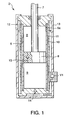
- FIG. 1 is a schematic longitudinal sectional view of a shock absorber in which a damping valve according to this invention is installed.
- FIG. 2 is a longitudinal sectional view of the damping valve.
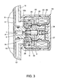
- FIG. 3 is similar to FIG. 2 but shows a magnetic path formed in the damping valve by a solenoid.
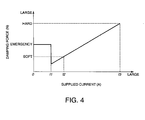
- FIG. 4 is a diagram showing a relationship between a damping force of the damping valve and a power current supplied to the solenoid.
- FIG. 5 is a longitudinal sectional view of a damping valve according to a second embodiment of this invention.
- a linear motion type shock absorber D comprises a cylinder 5, a piston 6 housed in the cylinder so as to be free to slide axially, a piston rod 7 fixed to the piston 6 and projecting axially from the cylinder 5, an inner tube 11 surrounding the cylinder 5, and an outer tube 13 surrounding the inner tube 11.
- the interior of the cylinder 5 is divided by the piston 6 into a rod side chamber 8 and a piston side chamber 9. These chambers 8, 9 are filled with working fluid. Oil or any other incompressible fluid may serve as the working fluid.
- the rod side chamber 8 communicates with a discharge passage 10, which passes through an annular space between the cylinder 5 and the inner tube 11, via a communication hole 5a formed on a tip of the cylinder 5.
- An annular space formed between the inner tube 11 and the outer tube 13 serves as a reservoir 12 in which the working fluid accumulates together with gas.
- the discharge passage 10 is connected to the reservoir 12 via a damping valve V1.
- the piston side chamber 9 and the reservoir 12 are connected via a check valve 14 which is installed in the bottom of the cylinder 5.
- the check valve 14 allows the working fluid to flow from the reservoir 12 to the piston side chamber 9 while preventing the working fluid from flowing in the opposite direction.
- the rod side chamber 8 and the piston side chamber 9 are connected via a check valve 15 which is installed in the piston 6.
- the check valve 15 allows the working fluid to flow from the piston side chamber 9 to the rod side chamber 8 through the piston 6 while preventing the working fluid from flowing in the opposite direction.
- This shock absorber D is a so-called uniflow type shock absorber in which the working fluid is always circulated in one direction irrespective of the direction of the piston stroke.
- the piston side chamber 9 decreases and the rod side chamber 8 enlarges.
- the working fluid in the piston side chamber 9 flows into the rod side chamber 8 through the check valve 15.
- the rod side chamber 8 enlarges, the total capacity of the rod side chamber 8 and the piston side chamber 9 decreases by the volume of the piston rod 7 that enters the cylinder 5 during the contraction stroke of the piston 6.
- This variation in the capacity of the cylinder 5 causes a part of the fluid in the rod side chamber 8 to be discharged into the reservoir 12 through the discharge passage 10 and the damping valve V1.
- the working fluid passing through the damping valve V1 generates a contraction damping force.
- the piston side chamber 9 enlarges and the rod side chamber 8 decreases. Accordingly, the working fluid in the reservoir 12 flows into the piston side chamber 9 through the check valve 14, and the working fluid in the rod side chamber 8 is discharged into the reservoir 12 through the discharge passage 10 and the damping valve V1. The working fluid passing through the damping valve V1 generates an elongation damping force.
- the shock absorber D when the shock absorber D operates, a part of the working fluid in the rod side chamber 8 is always discharged into the reservoir 12 through the damping valve V1 so as to generate a damping force, irrespective of the stroke direction of the piston 6.
- the magnitude of the contraction damping force and that of the elongation damping force can be made equal by setting the cross-sectional area of the piston rod 7 to be equal to half of the cross-sectional area of the cylinder 5.
- the damping valve V1 is disposed in a flow path P which connects the discharge passage 10 and the reservoir 12.
- the damping valve V1 comprises a normal state operation valve 1 and an emergency state operation valve 4 installed in a case 20.
- the normal state operation valve 1 comprises a valve body 2 fitted into a valve housing 16, an annular valve seat 18 formed as a part of the valve housing 16, a solenoid S which exerts a thrusting force on the valve body 2 towards the valve seat 18, and a spring 3 which biases the valve body 2 against the thrusting force of the solenoid S or in a direction to increase the flow cross-sectional area between the valve body 2 and the valve seat 18.
- the inner tube 11 has an opening in a lateral direction in the form of a sleeve 11a.
- the valve housing 16 has a cylindrical tip which is fitted into the sleeve 11 a.
- a seal member 19 is applied between the sleeve 11a and the cylindrical tip of the valve housing 16 so as to prevent the working fluid from leaking to the outside of the inner tube 11.
- a lateral hole 16a and a vertical hole 16b are formed through the valve housing 16. These holes 16a, 16b constitute the flow path P. An end of the lateral hole 16a opens onto the discharge passage 10 and another end of the lateral hole 16a has an opening on the opposite face of the valve housing 16 so as to accommodate the valve body 2.
- the lateral hole 16a has a small inner diameter part 16c which serves as the valve seat 18.
- the valve body 2 comprises a large diameter part 2a which is fitted into the lateral hole 16a, a small diameter part 2b which projects from a tip of the large diameter part 2a towards the valve seat 18, and a conical valve head 2c formed on a tip of the small diameter part 2b so as to be seated on the valve seat 18.
- the small diameter part 2b forms an annular space in the lateral hole 16a.
- the vertical hole 16b opens onto this annular space.
- the vertical hole 16b also has openings onto the outside of the valve housing 16.
- the spring 3 is disposed in the annular space between a step formed between the large diameter part 2a and the small diameter part 2b of the valve body 2, and a step formed by the small diameter part 16c in the valve housing 16.
- the solenoid S comprises a bobbin 22 fitted into the case 20 and a coil 21 wound onto the bobbin 22.
- the bobbin 22 is positioned by a flange 20c formed on the inner circumference of the case 20 and projecting inward.
- the bobbin 22 is formed in a cylindrical shape.
- a first fixed iron core 24 and a second fixed iron core 25 are fitted into the inner circumference of the bobbin 22.
- a spacer 26 made from a nonmagnetic material is interposed between the first fixed iron core 24 and the second fixed iron core 25.
- the first fixed iron core 24 is formed in a cylindrical shape having a bottom.
- the second fixed iron core 25 and the spacer 26 are formed in a cylindrical shape having openings at both ends, respectively.
- Cylindrical walls of the first fixed iron core 24, the spacer 26, and the second fixed iron core 25 are made to have an identical thickness such that these members 24-26 form one continuous cylinder fitted into the inner circumference of the bobbin 22.
- the case 20 is formed in a cylindrical shape having two open ends, one of which is closed by a lid 20b fixed by staking the edge of the case 20 inward. An end of the bobbin 22 and the bottom of the first fixed iron core 24 are supported by the lid 20b.
- the outer tube 13 has an opening 13a which surrounds the sleeve 11a.
- a tube 13b is fixed to the opening 13a by welding.
- the tube 13b provides structural support to the case 20 and the valve housing 16. Another open end of the case 20 is screwed onto the outer circumference of the tube 13b.
- a movable iron core 27 is fitted into the continuous cylinder constituted by the first fixed iron core 24, the spacer 26, and the second fixed iron core 25 so as to be free to slide axially.
- the rear end of the large diameter part 2a of the valve body also projects into this continuous cylinder from the valve housing 16.
- the movable iron core 27 is disposed between the rear end of the large diameter part 2a of the valve body 2 and the bottom of the first fixed iron core 24.
- a washer 29 made from a nonmagnetic material is interposed between the movable iron core 27 and the bottom of the first fixed iron core 24.
- the spring 3 which biases the valve body 2 in the direction to increase the flow cross-sectional area of the gap between the valve body 2 and the valve seat 18 causes the valve body 2 to push the movable iron core 27 towards the bottom of the first fixed iron core 24.
- the movable iron core 27 has a recess which has an opening directed towards the bottom of the first fixed iron core 24 so as to accommodate a spring 17 and a part of a spring force adjusting screw 30.
- the spring force adjusting screw 30 is screwed into a screw hole formed through the bottom of the first fixed iron core 24 and projects into the recess.
- the spring force adjusting screw 30 has a flange 30a on its outer circumference in the recess to support an end of the spring 17. The other end of the spring 17 is in contact with a bottom of the recess of the movable iron core 27.
- the initial spring load of the spring 17, exerted on the movable iron core 27, can be set arbitrarily by rotating the spring force adjusting screw 30 from the outside before fixing the lid 20b to the case 20. If the lid 20b is made detachable from the case 20, the spring force adjusting screw 30 can be manipulated at any time. Since the spring 3 and the spring 17 are arranged in series, rotating the spring force adjusting screw 30 adjusts not only the initial spring load of the spring 17 but also the initial spring load of the spring 3.
- the movable iron core 27 has a through-hole 27a to equalize fluid pressures acting on the two ends of the movable iron core 27.
- the movable iron core 27 is pushed against the first fixed iron core 24 by the biasing force of the spring 17 and stays in a retracted position in which the movable iron core 27 contacts the washer 29 when the solenoid S is not energized.
- the length of the spacer 26 is set such that a tip of the movable iron core 27 in the retracted position stays in contact with or nearby the second fixed iron core 25.
- the contact faces of the movable iron core 27 and the spacer 26 are formed in a conical shape such that magnetic flux formed by the solenoid S concentrates on the inner side of the contact face of the movable iron core 27.
- the movable iron core 27 can be displaced towards the valve body 16 while pushing the valve body 2 towards the valve seat 18. This displacement is limited when the movable iron core 27 comes into contact with a stopper 31 which is made from a nonmagnetic material and fitted onto the outer circumference of the valve body 16.
- the washer 29 and the stopper 31 are preferably made of synthetic resin in view of suppressing noise generated when the movable iron core 27 comes into contact with them.
- the valve housing 16 comprises a flange 16d and a large diameter part 16e on its outer circumference on both sides of the vertical hole 16b.
- the flange 16d is fitted into the tube 13b such that an outer circumferential part of the flange 16d comes into contact with a step 13c formed at an end of the tube 13b nearby the opening 13a.
- the flange 16d has through-holes 16f so as to connect the vertical hole 16b and the reservoir 12.
- a spacer 23 made from a nonmagnetic material is interposed between the flange 20c of the case 20 and the flange 16d.
- the flange 16d is gripped between the step 13c and the flange 20c via the spacer 23.
- the spacer 23 is formed in a cylindrical shape and has a flange 23a at an end which projects inward.
- the spacer 23 is fitted into the inner circumference of the tube 13b and a seal member 32 is applied between the spacer 23 and the tube 13b so as to prevent the working fluid in the flow path P from leaking to the outside of the tube 13b.
- a tip of the second fixed iron core 25 is caused to project from the bobbin 22 and fitted into the inner circumference of the flange 23a.
- the emergency state operation valve 4 is disposed in the spacer 23.
- the emergency state operation valve 4 comprises a valve body 28 and a spring 33.
- the valve body 28 is made from a magnetic material and functions as another movable iron core.
- the valve body 28 is formed in a cylindrical shape and fitted onto the outer circumference of the large diameter part 16e of the valve housing 16 so as to be free to slide axially.
- the valve body 28 has a flange part 28a on a tip facing the flange 16d of the valve housing 16.
- An annular projection 28b projecting towards the flange 16d is formed on the flange part 28a.
- the spring 33 is interposed between the flange part 28a and the flange 23a of the spacer 23. The valve body 28 is biased by the spring 33 towards the flange 16d. Accordingly, when the solenoid S is not energized, the valve body 28 is held in an advanced position in which the annular projection 28b contacts the flange 16d of the valve housing 16.
- the valve body 28 has orifices 28c that connect the inner space and the outer space of the valve body 28.
- the space delimited by the valve body 28 in the continuous cylinder constituted by the first fixed iron core 24, the spacer 26, and the second fixed iron core 25 is connected to the orifice 28c via a communicating hole 28d which is formed axially in the valve body 28.
- valve body 28 When, on the other hand, the valve body 28 is in a retracted position in which the valve body 28 comes into contact with the second fixed iron core 25, a gap formed between the annular projection 28b and the flange 16d allows the working fluid to flow between the vertical hole 16b and the reservoir 12 without exerting high resistance.
- valve housing 16 the tube 13b, the case 20, the lid 20b, the first fixed iron core 24, the movable iron core 27, the second fixed iron core 25, the valve body 28 of the emergency state operation valve 4, and the valve housing 16 are made from a magnetic material, and when the solenoid S is energized, a magnetic path is formed through these members as shown by the arrows in the figure.
- the movable iron core 27 and the valve body 28 of the emergency state operation valve 4 are attracted by the second fixed iron core 25.
- the power current supplied to the solenoid S exceeds a predetermined value, the magnetic force acting on the valve body 28 becomes greater than the biasing force of the spring 33, and therefore the valve body 28 is displaced to the retracted position in which the valve body 28 comes into contact with the second fixed iron core 25.
- the gap between the annular projection 28b and the flange 16d reaches a maximum. In this state, the emergency state operation valve 4 allows the working fluid to pass through the gap without generating a damping force.
- the movable iron core 27 is pushed by the spring 3 towards the bottom of the first fixed iron core 24. It is also pushed by the spring 17 in the opposite direction.
- the biasing force of the spring 3 is set greater than that of the spring 17, and when no magnetic force acts on the movable iron core 27, the movable iron core 27 is held in the retracted position as described above.
- the magnetic force acting on the movable iron core 27 becomes greater than the difference between the biasing forces of the springs 3 and 17.
- the movable iron core 27 then moves towards the valve housing 16 while pushing the valve body 2 of the normal state operation valve 1 towards the valve seat 18.
- the flow path P passing through the gap between the valve seat 18 and the valve head 2c of the valve body 2 is narrowed, and a damping force is generated when the working fluid passes through this gap.
- the magnitude of the generated damping force depends on the width of this gap, or in other words on the power current supplied to the solenoid S.
- a power current between values I2 and I3 is supplied to the solenoid S.
- the predetermined value is set at I1 , which is smaller than the values I2 and I3 .
- the movable iron core 27 is driven towards the valve housing 16 so as to narrow the gap between the valve seat 18 and the valve head 2c of the normal state operation valve 1.
- the normal state operation valve 1 thus generates a damping force corresponding to the power current supplied to the solenoid S. As the power current increases, the generated damping force increases as shown in the figure.
- the power current supplied to the solenoid S is not greater than the predetermined value I1 , the magnetic force acting on the movable iron core 27 is not sufficient to drive the movable iron core 27 from the retracted position, and hence the gap between the valve seat 18 and the valve head 2c stays at the maximum and the normal state operation valve 1 does not generate a damping force.
- the magnetic force acting on the valve body 28 is not sufficient to keep the valve body 28 in the retracted position against the biasing force of the spring 33, and the valve body 28 displaces to the advanced position in which the annular projection 28b comes into contact with the flange 16d.
- the orifices 28c form the only communicating path between the vertical hole 16b and the reservoir 12. Due to the limited cross-sectional area of the orifices 28c, the emergency state operation valve 4 generates a great damping force as the working fluid passes through the orifices 28c.
- the damping force characteristic of the shock absorber D is constant, as shown in the figure, irrespective of the power current supplied to the solenoid S.
- the communicating hole 28d is not blocked by the second fixed iron core 25, and communication between the space in the second fixed iron core 25 and the flow path P is maintained.
- the communicating hole 28d therefore prevents the working fluid in this space from blocking displacement of the movable iron core 27.
- the damping force generated in the normal state operation valve 1 and the damping force generated by the emergency state operation valve 4 are controlled separately using the single solenoid S. Switch-over between the normal state operation valve 1 and the emergency state operation valve 4 is therefore performed without fail.
- the damping valve V1 ensures generation of an expected damping force during an emergency operation while enabling wide-range adjustment of the damping force during a normal operation.
- the initial load acting on the valve body 2 of the normal state operation valve 1 can be varied widely by rotating the spring force adjusting screw 30, without affecting the operation characteristics of the emergency state operation valve 4.
- a damping valve V2 further comprises a main valve 40.
- the damping valve V2 comprises the normal state operation valve 1 and the emergency state operation valve 4 which have identical constructions to those of the first embodiment, the normal state operation valve 1 in the damping valve V2 is provided not for generating a damping force but for regulating a back pressure applied to the main valve 40 when the damping valve V2 operates normally with the power current supplied to the solenoid S.
- the emergency state operation valve 4 in the damping valve V2 has a function to regulate the back pressure applied to the main valve 40 in an emergency state where the solenoid S is supplied with a poor or no power current.
- the main valve 40 comprises an adaptor 41.
- the adaptor 41 comprises a base portion 41a fitted into the sleeve 11a and a shaft portion 41b onto which the tip of the valve housing 16 is screwed.
- a seal member 45 is applied between the sleeve 11a and the base portion 41a so as to prevent the working fluid from leaking to the outside of the sleeve 11a.
- a lateral hole 41c connected to the lateral hole 16a of the valve housing 16 is formed in the shaft portion 41b.
- a valve body 46 in the form of a leaf is fitted onto the outer circumference of the shaft portion 41b. The inner circumferential portion of the valve body 46 is gripped between the adaptor 41 and the tip of the valve housing 16.
- Main passages 43 are formed through the adaptor 41 to lead the working fluid from the discharge passage 10 to the valve body 46.
- the adaptor 41 comprises a valve seat 44 on which the outer circumferential portion of the valve body 46 is seated.
- the outer circumferential portion of the valve body 46 lifts from the valve seat 44 according to a balance of the forces exerted thereon.
- the working oil in the main passages 43 flows directly into the reservoir 12 without passing through the normal state operation valve 1 or the emergency state operation valve 4.
- the adaptor 41 also has an inlet orifice 42 in its center so as to connect the discharge passage 10 to the lateral hole 41c.
- the orifice 42 may be replaced by a choke.
- the flow path P is constituted by the inlet orifice 42, the lateral hole 41c, the lateral hole 16a, the normal state operation valve 1, the vertical hole 16b, and the emergency state operation valve 4.
- the main valve 40 bypasses the flow path P and connects the discharge passage 10 to the reservoir 12 directly.
- a slider 47 having a flange 47a is fitted onto the outer circumference of the tip of the valve housing 16 so as to be free to slide axially.
- a spring 48 is gripped between the flange 47a and the flange 16d of the valve housing 16 so as to bias the slider 47 towards the outer circumferential part of the valve body 46.
- the valve housing 16 has a notch in the outer circumferential part of the tip so as to form a back pressure chamber 49 on the inside of the slider 47.
- the back pressure chamber 49 exerts a back pressure on the valve body 46. It should be noted that the function required of the slider 47 is to shut off the back pressure chamber 49 from the outside.
- the spring force of the spring 48 should be set at or in the vicinity of a minimum value at which contact can be maintained between the slider 47 and the valve body 46.
- the back pressure chamber 49 is connected to the lateral hole 41c via a through-hole 16h which traverses the tip of the valve housing 16 and a through-hole 41d which traverses the shaft portion 41b of the adaptor 41.
- the back pressure is lower than the fluid pressure in the discharge passage 10 and a differential pressure acts on the valve body 46 so as to lift the valve body 46 from the valve seat 44.
- the working fluid in the discharge passage 10 is then discharged into the reservoir 12 through the main valve 40 and generates a damping force when it passes through the gap formed between the valve body 46 and the valve seat 44.
- the magnitude of the damping force depends on the differential pressure acting on the valve body 46.
- the differential pressure is adjusted by the normal state operation valve 1, which operates according to the power current supplied to the solenoid S.
- the damping force generated in the main valve 40 can therefore be adjusted by varying the power current supplied to the solenoid S.
- the back pressure applied to the valve body 46 is controlled by the normal state operation valve 1 without being affected by the flow rate of the main valve 40.
- the damping valve V2 is operated normally, therefore, the damping force can be controlled precisely by varying the power current supplied to the solenoid S, and hence, the relationship between the generated damping force and the power current supplied to the solenoid S is perfectly linear, as shown in FIG. 4 , even when the stroke speed of the piston 6 is low.
- valve body 2 of the normal state operation valve 1 displaces to the retracted position in accordance with the biasing force of the spring 3
- valve body 28 of the emergency state operation valve 4 displaces to the advanced position in accordance with the biasing force of the spring 33.
- the gap between the valve seat 18 and the valve head 2c reaches a maximum and the working fluid passes this gap generating almost no pressure loss.
- the gap between the flange 16d and the annular projection 28b is closed and the working fluid in the vertical hole 16b must pass the orifices 28c to reach to the reservoir 12.
- the back pressure in the back pressure chamber 49 is determined by the flow resistance of the orifice 42 and the flow resistance of the orifices 28c. Specifically, when the flow resistance of the orifice 42 is relatively large with respect to the flow resistance of the orifices 28c, the back pressure in the back pressure chamber 49 is relatively low. When the flow resistance of the orifice 42 is relatively small with respect to the flow resistance of the orifices 28c, the back pressure in the back pressure chamber 49 is relatively high.
- the damping force characteristic of the main valve 40 in the emergency state can be preset arbitrarily depending on the dimensions of the orifice 42.
- the back pressure of the main valve 40 is controlled by the normal state operation valve 1 in accordance with the power current supplied to the solenoid S in the normal state and controlled by the emergency state operation valve 4 to a predetermined pressure in the emergency state.
- the generated damping force of the damping valve V2 can be controlled precisely, irrespective of the stroke speed of the piston 6.
- the tube 13b, the valve housing 16, the case 20, the lid 20b, the first fixed iron core 24, the second fixed iron core 25, the movable iron core 27, and the valve body 28 of the emergency state operation valve 4 constitute a magnetic path forming member.
- the magnetic path forming member and the spacer 26 constitute a driving mechanism of the normal state operation valve 1 and the emergency state operation valve 4.
- valve body 2 takes the shape of a poppet valve.
- valve body 2 may be formed in any shape including a spool shape as long as it can be driven by the solenoid S.
- valve body 46 of the main valve 40 is provided in the form of a leaf valve.
- This valve body form helps to prevent the size of the damping valve V2 from increasing, but the form of the valve body 46 is not limited to a leaf valve.
- the valve body 46 may be formed in the shape of a spool valve or a poppet valve.
Abstract
Description
- This invention relates to a damping valve provided in a shock absorber for the purpose of generating a damping force by exerting resistance on a flow of fluid discharged from a cylinder to a reservoir in accordance with the contraction/elongation of the shock absorber.
- A linear motion type shock absorber comprises a damping valve which generates a damping force by exerting resistance on a flow of fluid discharged from a cylinder to a reservoir in accordance with an operation of the shock absorber.
- Japanese Patent Serial No.
3064964 - The damping valve according to this prior art comprises a rod having a ring groove formed by two side walls on its outer circumference, a plate having a smaller thickness than the width of the ring groove and provided with a hole surrounding the ring groove, a solenoid which biases the rod in one direction when energized, and a spring which biases the rod against a thrusting force exerted by the solenoid. The fluid discharged from the cylinder to the reservoir passes through a space between the ring groove and the plate.
- When the solenoid is energized, the rod displaces in a direction against the spring and one side wall of the ring groove approaches the plate so as to narrow a first gap formed therebetween. As a result, the damping valve generates a damping force on the basis of a flow resistance of this first gap. When the solenoid is not energized, the rod displaces according to a biasing force of the spring in the opposite direction and the other side wall of the ring groove approaches the plate so as to narrow a second gap formed therebetween. As a result, the damping valve generates a damping force on the basis of a flow resistance of this second gap.
- When the shock absorber operates normally, a power current is always supplied from a power current source to the solenoid and the damping force is generated in the first gap. By varying the power current, the width of the gap varies. Different settings of damping characteristics are thereby enabled. The operation position of the damping valve in which the first gap generates a damping force is referred to as a normal valve position.
- When, on the other hand, the power current is not supplied to the solenoid due to, for example, trouble in the power current source, the rod biased by the spring displaces to narrow the second gap until the rod contacts a stopper and its further displacement is thereby prevented. In this state, the damping force is generated in the second gap. The width of the second gap is determined by the stopper. The stopper is supported by a screw feed mechanism such that its position can be arbitrarily adjusted. The operation position of the damping valve in which the second gap generates a damping force is referred to as an emergency valve position.
- In the damping valve according to the prior art, a situation in which the stopper is positioned such that the second gap remains greater than the first gap may arise. In this case, the damping force is generated by the first gap despite the fact that the solenoid is not energized, and hence the emergency valve position does not function properly. The adjustable range in the flow cross-sectional area of the first gap in the normal valve position is also narrowed by the stopper, and therefore an optimal damping force in the normal valve position may not be obtained.
- It is therefore an object of this invention to ensure generation of an expected damping force during an emergency operation of a damping valve while enabling wide-range adjustment of the damping force during a normal operation of the same.
- To achieve the above object, this invention provides a damping valve comprising a flow path of fluid, a normal state operation valve disposed in the flow path, an emergency state operation valve disposed in the flow path downstream of the normal state operation valve, a solenoid which generates a magnetic force according to a supply of a power current, and a driving mechanism which varies a flow resistance of the normal state operation valve and a flow resistance of the emergency state operation valve separately using a magnetic force generated by the solenoid.
- The details as well as other features and advantages of this invention are set forth in the remainder of the specification and are shown in the accompanying drawings.
-
FIG. 1 is a schematic longitudinal sectional view of a shock absorber in which a damping valve according to this invention is installed. -
FIG. 2 is a longitudinal sectional view of the damping valve. -
FIG. 3 is similar toFIG. 2 but shows a magnetic path formed in the damping valve by a solenoid. -
FIG. 4 is a diagram showing a relationship between a damping force of the damping valve and a power current supplied to the solenoid. -
FIG. 5 is a longitudinal sectional view of a damping valve according to a second embodiment of this invention. - Referring to
FIG. 1 of the drawings, a linear motion type shock absorber D comprises acylinder 5, apiston 6 housed in the cylinder so as to be free to slide axially, apiston rod 7 fixed to thepiston 6 and projecting axially from thecylinder 5, aninner tube 11 surrounding thecylinder 5, and anouter tube 13 surrounding theinner tube 11. - The interior of the
cylinder 5 is divided by thepiston 6 into arod side chamber 8 and apiston side chamber 9. Thesechambers rod side chamber 8 communicates with adischarge passage 10, which passes through an annular space between thecylinder 5 and theinner tube 11, via acommunication hole 5a formed on a tip of thecylinder 5. An annular space formed between theinner tube 11 and theouter tube 13 serves as areservoir 12 in which the working fluid accumulates together with gas. Thedischarge passage 10 is connected to thereservoir 12 via a damping valve V1. - The
piston side chamber 9 and thereservoir 12 are connected via acheck valve 14 which is installed in the bottom of thecylinder 5. Thecheck valve 14 allows the working fluid to flow from thereservoir 12 to thepiston side chamber 9 while preventing the working fluid from flowing in the opposite direction. - The
rod side chamber 8 and thepiston side chamber 9 are connected via acheck valve 15 which is installed in thepiston 6. Thecheck valve 15 allows the working fluid to flow from thepiston side chamber 9 to therod side chamber 8 through thepiston 6 while preventing the working fluid from flowing in the opposite direction. - This shock absorber D is a so-called uniflow type shock absorber in which the working fluid is always circulated in one direction irrespective of the direction of the piston stroke.
- Specifically, when the
piston 6 performs a contraction stroke, or in other words when thepiston 6 strokes downward in the figure, thepiston side chamber 9 decreases and therod side chamber 8 enlarges. The working fluid in thepiston side chamber 9 flows into therod side chamber 8 through thecheck valve 15. Although therod side chamber 8 enlarges, the total capacity of therod side chamber 8 and thepiston side chamber 9 decreases by the volume of thepiston rod 7 that enters thecylinder 5 during the contraction stroke of thepiston 6. This variation in the capacity of thecylinder 5 causes a part of the fluid in therod side chamber 8 to be discharged into thereservoir 12 through thedischarge passage 10 and the damping valve V1. The working fluid passing through the damping valve V1 generates a contraction damping force. - When the
piston 6 performs an elongation stroke, or in other words when thepiston 6 strokes upward in the figure, thepiston side chamber 9 enlarges and therod side chamber 8 decreases. Accordingly, the working fluid in thereservoir 12 flows into thepiston side chamber 9 through thecheck valve 14, and the working fluid in therod side chamber 8 is discharged into thereservoir 12 through thedischarge passage 10 and the damping valve V1. The working fluid passing through the damping valve V1 generates an elongation damping force. - As described above, when the shock absorber D operates, a part of the working fluid in the
rod side chamber 8 is always discharged into thereservoir 12 through the damping valve V1 so as to generate a damping force, irrespective of the stroke direction of thepiston 6. The magnitude of the contraction damping force and that of the elongation damping force can be made equal by setting the cross-sectional area of thepiston rod 7 to be equal to half of the cross-sectional area of thecylinder 5. - Referring to
FIG. 2 , the damping valve V1 is disposed in a flow path P which connects thedischarge passage 10 and thereservoir 12. The damping valve V1 comprises a normalstate operation valve 1 and an emergencystate operation valve 4 installed in acase 20. - The normal
state operation valve 1 comprises avalve body 2 fitted into avalve housing 16, anannular valve seat 18 formed as a part of thevalve housing 16, a solenoid S which exerts a thrusting force on thevalve body 2 towards thevalve seat 18, and aspring 3 which biases thevalve body 2 against the thrusting force of the solenoid S or in a direction to increase the flow cross-sectional area between thevalve body 2 and thevalve seat 18. - The
inner tube 11 has an opening in a lateral direction in the form of asleeve 11a. Thevalve housing 16 has a cylindrical tip which is fitted into thesleeve 11 a. Aseal member 19 is applied between thesleeve 11a and the cylindrical tip of thevalve housing 16 so as to prevent the working fluid from leaking to the outside of theinner tube 11. - A
lateral hole 16a and avertical hole 16b are formed through thevalve housing 16. Theseholes lateral hole 16a opens onto thedischarge passage 10 and another end of thelateral hole 16a has an opening on the opposite face of thevalve housing 16 so as to accommodate thevalve body 2. Thelateral hole 16a has a smallinner diameter part 16c which serves as thevalve seat 18. - The
valve body 2 comprises alarge diameter part 2a which is fitted into thelateral hole 16a, asmall diameter part 2b which projects from a tip of thelarge diameter part 2a towards thevalve seat 18, and aconical valve head 2c formed on a tip of thesmall diameter part 2b so as to be seated on thevalve seat 18. - The
small diameter part 2b forms an annular space in thelateral hole 16a. Thevertical hole 16b opens onto this annular space. Thevertical hole 16b also has openings onto the outside of thevalve housing 16. - The
spring 3 is disposed in the annular space between a step formed between thelarge diameter part 2a and thesmall diameter part 2b of thevalve body 2, and a step formed by thesmall diameter part 16c in thevalve housing 16. - The solenoid S comprises a
bobbin 22 fitted into thecase 20 and acoil 21 wound onto thebobbin 22. Thebobbin 22 is positioned by aflange 20c formed on the inner circumference of thecase 20 and projecting inward. Thebobbin 22 is formed in a cylindrical shape. A first fixediron core 24 and a secondfixed iron core 25 are fitted into the inner circumference of thebobbin 22. - A
spacer 26 made from a nonmagnetic material is interposed between the firstfixed iron core 24 and the secondfixed iron core 25. The firstfixed iron core 24 is formed in a cylindrical shape having a bottom. The secondfixed iron core 25 and thespacer 26 are formed in a cylindrical shape having openings at both ends, respectively. - Cylindrical walls of the first
fixed iron core 24, thespacer 26, and the secondfixed iron core 25 are made to have an identical thickness such that these members 24-26 form one continuous cylinder fitted into the inner circumference of thebobbin 22. - The
case 20 is formed in a cylindrical shape having two open ends, one of which is closed by alid 20b fixed by staking the edge of thecase 20 inward. An end of thebobbin 22 and the bottom of the firstfixed iron core 24 are supported by thelid 20b. - The
outer tube 13 has anopening 13a which surrounds thesleeve 11a. Atube 13b is fixed to theopening 13a by welding. Thetube 13b provides structural support to thecase 20 and thevalve housing 16. Another open end of thecase 20 is screwed onto the outer circumference of thetube 13b. - A
movable iron core 27 is fitted into the continuous cylinder constituted by the firstfixed iron core 24, thespacer 26, and the secondfixed iron core 25 so as to be free to slide axially. The rear end of thelarge diameter part 2a of the valve body also projects into this continuous cylinder from thevalve housing 16. Themovable iron core 27 is disposed between the rear end of thelarge diameter part 2a of thevalve body 2 and the bottom of the firstfixed iron core 24. Awasher 29 made from a nonmagnetic material is interposed between themovable iron core 27 and the bottom of the firstfixed iron core 24. Thespring 3 which biases thevalve body 2 in the direction to increase the flow cross-sectional area of the gap between thevalve body 2 and thevalve seat 18 causes thevalve body 2 to push themovable iron core 27 towards the bottom of the firstfixed iron core 24. - The
movable iron core 27 has a recess which has an opening directed towards the bottom of the firstfixed iron core 24 so as to accommodate aspring 17 and a part of a springforce adjusting screw 30. The springforce adjusting screw 30 is screwed into a screw hole formed through the bottom of the firstfixed iron core 24 and projects into the recess. The springforce adjusting screw 30 has aflange 30a on its outer circumference in the recess to support an end of thespring 17. The other end of thespring 17 is in contact with a bottom of the recess of themovable iron core 27. - According to the above support structure of the
movable iron core 27, the initial spring load of thespring 17, exerted on themovable iron core 27, can be set arbitrarily by rotating the springforce adjusting screw 30 from the outside before fixing thelid 20b to thecase 20. If thelid 20b is made detachable from thecase 20, the springforce adjusting screw 30 can be manipulated at any time. Since thespring 3 and thespring 17 are arranged in series, rotating the springforce adjusting screw 30 adjusts not only the initial spring load of thespring 17 but also the initial spring load of thespring 3. - The
movable iron core 27 has a through-hole 27a to equalize fluid pressures acting on the two ends of themovable iron core 27. - The
movable iron core 27 is pushed against the firstfixed iron core 24 by the biasing force of thespring 17 and stays in a retracted position in which themovable iron core 27 contacts thewasher 29 when the solenoid S is not energized. The length of thespacer 26 is set such that a tip of themovable iron core 27 in the retracted position stays in contact with or nearby the secondfixed iron core 25. Further, the contact faces of themovable iron core 27 and thespacer 26 are formed in a conical shape such that magnetic flux formed by the solenoid S concentrates on the inner side of the contact face of themovable iron core 27. - The
movable iron core 27 can be displaced towards thevalve body 16 while pushing thevalve body 2 towards thevalve seat 18. This displacement is limited when themovable iron core 27 comes into contact with astopper 31 which is made from a nonmagnetic material and fitted onto the outer circumference of thevalve body 16. - The
washer 29 and thestopper 31 are preferably made of synthetic resin in view of suppressing noise generated when themovable iron core 27 comes into contact with them. - The
valve housing 16 comprises aflange 16d and alarge diameter part 16e on its outer circumference on both sides of thevertical hole 16b. Theflange 16d is fitted into thetube 13b such that an outer circumferential part of theflange 16d comes into contact with a step 13c formed at an end of thetube 13b nearby theopening 13a. Theflange 16d has through-holes 16f so as to connect thevertical hole 16b and thereservoir 12. - A
spacer 23 made from a nonmagnetic material is interposed between theflange 20c of thecase 20 and theflange 16d. By screwing thecase 20 onto the outer circumference of thetube 13b, theflange 16d is gripped between the step 13c and theflange 20c via thespacer 23. - The
spacer 23 is formed in a cylindrical shape and has aflange 23a at an end which projects inward. Thespacer 23 is fitted into the inner circumference of thetube 13b and a seal member 32 is applied between thespacer 23 and thetube 13b so as to prevent the working fluid in the flow path P from leaking to the outside of thetube 13b. - A tip of the second
fixed iron core 25 is caused to project from thebobbin 22 and fitted into the inner circumference of theflange 23a. - The emergency
state operation valve 4 is disposed in thespacer 23. The emergencystate operation valve 4 comprises avalve body 28 and aspring 33. - The
valve body 28 is made from a magnetic material and functions as another movable iron core. Thevalve body 28 is formed in a cylindrical shape and fitted onto the outer circumference of thelarge diameter part 16e of thevalve housing 16 so as to be free to slide axially. - The
valve body 28 has aflange part 28a on a tip facing theflange 16d of thevalve housing 16. Anannular projection 28b projecting towards theflange 16d is formed on theflange part 28a. Thespring 33 is interposed between theflange part 28a and theflange 23a of thespacer 23. Thevalve body 28 is biased by thespring 33 towards theflange 16d. Accordingly, when the solenoid S is not energized, thevalve body 28 is held in an advanced position in which theannular projection 28b contacts theflange 16d of thevalve housing 16. - The
valve body 28 hasorifices 28c that connect the inner space and the outer space of thevalve body 28. The space delimited by thevalve body 28 in the continuous cylinder constituted by the firstfixed iron core 24, thespacer 26, and the secondfixed iron core 25 is connected to theorifice 28c via a communicatinghole 28d which is formed axially in thevalve body 28. When thevalve body 28 is in the advanced position, thevertical hole 16b and thereservoir 12 is connected only through theorifices 28c. When, on the other hand, thevalve body 28 is in a retracted position in which thevalve body 28 comes into contact with the secondfixed iron core 25, a gap formed between theannular projection 28b and theflange 16d allows the working fluid to flow between thevertical hole 16b and thereservoir 12 without exerting high resistance. - Referring to
FIG. 3 , thevalve housing 16, thetube 13b, thecase 20, thelid 20b, the firstfixed iron core 24, themovable iron core 27, the secondfixed iron core 25, thevalve body 28 of the emergencystate operation valve 4, and thevalve housing 16 are made from a magnetic material, and when the solenoid S is energized, a magnetic path is formed through these members as shown by the arrows in the figure. - As a result, the
movable iron core 27 and thevalve body 28 of the emergencystate operation valve 4 are attracted by the secondfixed iron core 25. When the power current supplied to the solenoid S exceeds a predetermined value, the magnetic force acting on thevalve body 28 becomes greater than the biasing force of thespring 33, and therefore thevalve body 28 is displaced to the retracted position in which thevalve body 28 comes into contact with the secondfixed iron core 25. When thevalve body 28 is in the retracted position, the gap between theannular projection 28b and theflange 16d reaches a maximum. In this state, the emergencystate operation valve 4 allows the working fluid to pass through the gap without generating a damping force. - The
movable iron core 27 is pushed by thespring 3 towards the bottom of the firstfixed iron core 24. It is also pushed by thespring 17 in the opposite direction. The biasing force of thespring 3 is set greater than that of thespring 17, and when no magnetic force acts on themovable iron core 27, themovable iron core 27 is held in the retracted position as described above. - As the power current supplied to the solenoid S increases, the magnetic force acting on the
movable iron core 27 becomes greater than the difference between the biasing forces of thesprings movable iron core 27 then moves towards thevalve housing 16 while pushing thevalve body 2 of the normalstate operation valve 1 towards thevalve seat 18. - As a result, the flow path P passing through the gap between the
valve seat 18 and thevalve head 2c of thevalve body 2 is narrowed, and a damping force is generated when the working fluid passes through this gap. The magnitude of the generated damping force depends on the width of this gap, or in other words on the power current supplied to the solenoid S. - Referring to
FIG. 4 , in a normal operation of the shock absorber D, a power current between values I2 and I3 is supplied to the solenoid S. Herein, the predetermined value is set at I1, which is smaller than the values I2 and I3. When a power current between I2 and I3 is supplied to the solenoid S, the emergencystate operation valve 4 keeps thevalve body 28 in the retracted position such that no resistance is exerted on the working fluid passing through the emergencystate operation valve 4. - On the other hand, the
movable iron core 27 is driven towards thevalve housing 16 so as to narrow the gap between thevalve seat 18 and thevalve head 2c of the normalstate operation valve 1. The normalstate operation valve 1 thus generates a damping force corresponding to the power current supplied to the solenoid S. As the power current increases, the generated damping force increases as shown in the figure. - When, on the other hand, the power current supplied to the solenoid S is not greater than the predetermined value I1, the magnetic force acting on the
movable iron core 27 is not sufficient to drive themovable iron core 27 from the retracted position, and hence the gap between thevalve seat 18 and thevalve head 2c stays at the maximum and the normalstate operation valve 1 does not generate a damping force. - In the emergency
state operation valve 4, the magnetic force acting on thevalve body 28 is not sufficient to keep thevalve body 28 in the retracted position against the biasing force of thespring 33, and thevalve body 28 displaces to the advanced position in which theannular projection 28b comes into contact with theflange 16d. In this state, theorifices 28c form the only communicating path between thevertical hole 16b and thereservoir 12. Due to the limited cross-sectional area of theorifices 28c, the emergencystate operation valve 4 generates a great damping force as the working fluid passes through theorifices 28c. As long as the power current supplied to the solenoid S is smaller than the predetermined value I1, the damping force characteristic of the shock absorber D is constant, as shown in the figure, irrespective of the power current supplied to the solenoid S. - It should be noted that even when the
valve body 28 is in the retracted position, the communicatinghole 28d is not blocked by the secondfixed iron core 25, and communication between the space in the secondfixed iron core 25 and the flow path P is maintained. The communicatinghole 28d therefore prevents the working fluid in this space from blocking displacement of themovable iron core 27. - The above situation also occurs in a state where no power current is supplied to the solenoid S.
- As described above, in the damping valve V1 according to this invention, the damping force generated in the normal
state operation valve 1 and the damping force generated by the emergencystate operation valve 4 are controlled separately using the single solenoid S. Switch-over between the normalstate operation valve 1 and the emergencystate operation valve 4 is therefore performed without fail. - As a result, the damping valve V1 ensures generation of an expected damping force during an emergency operation while enabling wide-range adjustment of the damping force during a normal operation.
- The initial load acting on the
valve body 2 of the normalstate operation valve 1 can be varied widely by rotating the springforce adjusting screw 30, without affecting the operation characteristics of the emergencystate operation valve 4. - Referring to
FIG. 5 , a second embodiment of this invention will be described. - A damping valve V2 according to this embodiment further comprises a
main valve 40. Although the damping valve V2 comprises the normalstate operation valve 1 and the emergencystate operation valve 4 which have identical constructions to those of the first embodiment, the normalstate operation valve 1 in the damping valve V2 is provided not for generating a damping force but for regulating a back pressure applied to themain valve 40 when the damping valve V2 operates normally with the power current supplied to the solenoid S. The emergencystate operation valve 4 in the damping valve V2 has a function to regulate the back pressure applied to themain valve 40 in an emergency state where the solenoid S is supplied with a poor or no power current. - The
main valve 40 comprises anadaptor 41. Theadaptor 41 comprises abase portion 41a fitted into thesleeve 11a and ashaft portion 41b onto which the tip of thevalve housing 16 is screwed. Aseal member 45 is applied between thesleeve 11a and thebase portion 41a so as to prevent the working fluid from leaking to the outside of thesleeve 11a. Alateral hole 41c connected to thelateral hole 16a of thevalve housing 16 is formed in theshaft portion 41b. Avalve body 46 in the form of a leaf is fitted onto the outer circumference of theshaft portion 41b. The inner circumferential portion of thevalve body 46 is gripped between theadaptor 41 and the tip of thevalve housing 16. -
Main passages 43 are formed through theadaptor 41 to lead the working fluid from thedischarge passage 10 to thevalve body 46. Theadaptor 41 comprises avalve seat 44 on which the outer circumferential portion of thevalve body 46 is seated. The outer circumferential portion of thevalve body 46 lifts from thevalve seat 44 according to a balance of the forces exerted thereon. When the outer circumferential portion of thevalve body 46 is lifted from thevalve seat 44, the working oil in themain passages 43 flows directly into thereservoir 12 without passing through the normalstate operation valve 1 or the emergencystate operation valve 4. - The
adaptor 41 also has aninlet orifice 42 in its center so as to connect thedischarge passage 10 to thelateral hole 41c. Theorifice 42 may be replaced by a choke. In this embodiment, the flow path P is constituted by theinlet orifice 42, thelateral hole 41c, thelateral hole 16a, the normalstate operation valve 1, thevertical hole 16b, and the emergencystate operation valve 4. Themain valve 40 bypasses the flow path P and connects thedischarge passage 10 to thereservoir 12 directly. - A
slider 47 having aflange 47a is fitted onto the outer circumference of the tip of thevalve housing 16 so as to be free to slide axially. Aspring 48 is gripped between theflange 47a and theflange 16d of thevalve housing 16 so as to bias theslider 47 towards the outer circumferential part of thevalve body 46. - The
valve housing 16 has a notch in the outer circumferential part of the tip so as to form aback pressure chamber 49 on the inside of theslider 47. Theback pressure chamber 49 exerts a back pressure on thevalve body 46. It should be noted that the function required of theslider 47 is to shut off theback pressure chamber 49 from the outside. The spring force of thespring 48 should be set at or in the vicinity of a minimum value at which contact can be maintained between theslider 47 and thevalve body 46. - The
back pressure chamber 49 is connected to thelateral hole 41c via a through-hole 16h which traverses the tip of thevalve housing 16 and a through-hole 41d which traverses theshaft portion 41b of theadaptor 41. - When the damping valve V2 operates normally, a power current between the values I2 and I3 is supplied to the solenoid S. The
movable iron core 27 drives thevalve body 2 towards thevalve seat 18 such that thevalve head 2c is seated on thevalve seat 18. As thepiston 6 performs a contraction stroke or an elongation stroke, the fluid pressure in thedischarge passage 10 rises such that the fluid pressure is exerted as an opening pressure on thevalve body 2 to lift thevalve head 2c from thevalve seat 18. - When the
valve body 2 is lifted from thevalve seat 18, a part of the working fluid in thedischarge passage 10 flows into thereservoir 12 through theorifice 42 and the gap between thevalve seat 18 and thevalve head 2c. In this state, the pressure in thelateral hole 41c is introduced into theback pressure chamber 49 through the through-holes - As a result of the pressure loss in the
orifice 42, the back pressure is lower than the fluid pressure in thedischarge passage 10 and a differential pressure acts on thevalve body 46 so as to lift thevalve body 46 from thevalve seat 44. - As the fluid pressure in the
discharge passage 10 increases, the differential pressure exceeds the opening pressure of thevalve body 46 and thevalve body 46 is lifted from thevalve seat 44. - The working fluid in the
discharge passage 10 is then discharged into thereservoir 12 through themain valve 40 and generates a damping force when it passes through the gap formed between thevalve body 46 and thevalve seat 44. The magnitude of the damping force depends on the differential pressure acting on thevalve body 46. The differential pressure is adjusted by the normalstate operation valve 1, which operates according to the power current supplied to the solenoid S. The damping force generated in themain valve 40 can therefore be adjusted by varying the power current supplied to the solenoid S. - Specifically, by increasing the power current supplied to the solenoid S, the pressure loss in the normal
state operation valve 1 increases and the back pressure in theback pressure chamber 49 increases. Accordingly, the damping force generated in themain valve 40 increases. By decreasing the power current supplied to the solenoid S, the pressure loss in the normalstate operation valve 1 decreases and the back pressure in theback pressure chamber 49 decreases. Accordingly, the damping force generated in themain valve 40 decreases. - As can be understood from the above, the back pressure applied to the
valve body 46 is controlled by the normalstate operation valve 1 without being affected by the flow rate of themain valve 40. As long as the damping valve V2 is operated normally, therefore, the damping force can be controlled precisely by varying the power current supplied to the solenoid S, and hence, the relationship between the generated damping force and the power current supplied to the solenoid S is perfectly linear, as shown inFIG. 4 , even when the stroke speed of thepiston 6 is low. - Further, since the back pressure is controlled using the magnetic force of the solenoid S to control the generated damping force of this damping valve V2, fluctuation in the damping force can be suppressed.
- When, on the other hand, the power current supplied to the solenoid S becomes smaller than the predetermined value I1 or reaches zero, no effective magnetic force is exerted on the
movable iron core 27 and thevalve body 28 of the emergencystate operation valve 4. - As a result, the
valve body 2 of the normalstate operation valve 1 displaces to the retracted position in accordance with the biasing force of thespring 3, and thevalve body 28 of the emergencystate operation valve 4 displaces to the advanced position in accordance with the biasing force of thespring 33. - In the retracted position of the
valve body 2, the gap between thevalve seat 18 and thevalve head 2c reaches a maximum and the working fluid passes this gap generating almost no pressure loss. In the advanced position of thevalve body 28, the gap between theflange 16d and theannular projection 28b is closed and the working fluid in thevertical hole 16b must pass theorifices 28c to reach to thereservoir 12. - In this state, the back pressure in the
back pressure chamber 49 is determined by the flow resistance of theorifice 42 and the flow resistance of theorifices 28c. Specifically, when the flow resistance of theorifice 42 is relatively large with respect to the flow resistance of theorifices 28c, the back pressure in theback pressure chamber 49 is relatively low. When the flow resistance of theorifice 42 is relatively small with respect to the flow resistance of theorifices 28c, the back pressure in theback pressure chamber 49 is relatively high. - The damping force characteristic of the
main valve 40 in the emergency state can be preset arbitrarily depending on the dimensions of theorifice 42. - In this damping valve V2, the back pressure of the
main valve 40 is controlled by the normalstate operation valve 1 in accordance with the power current supplied to the solenoid S in the normal state and controlled by the emergencystate operation valve 4 to a predetermined pressure in the emergency state. - Since the damping force characteristic obtained through the above control is not affected by the flow rate of the
main valve 40, the generated damping force of the damping valve V2 can be controlled precisely, irrespective of the stroke speed of thepiston 6. - In the embodiments described above, the
tube 13b, thevalve housing 16, thecase 20, thelid 20b, the firstfixed iron core 24, the secondfixed iron core 25, themovable iron core 27, and thevalve body 28 of the emergencystate operation valve 4 constitute a magnetic path forming member. The magnetic path forming member and thespacer 26 constitute a driving mechanism of the normalstate operation valve 1 and the emergencystate operation valve 4. - The contents of Tokugan 2008-067353 with a filing date of March 17, 2008 in Japan, are hereby incorporated by reference.
- Although the invention has been described above with reference to certain embodiments, the invention is not limited to the embodiments described above. Modifications and variations of the embodiments described above will occur to those skilled in the art, within the scope of the claims.
- For example, in the embodiments described above, the
valve body 2 takes the shape of a poppet valve. However, thevalve body 2 may be formed in any shape including a spool shape as long as it can be driven by the solenoid S. - With respect to the driving mechanism of the normal
state operation valve 1 and the emergencystate operation valve 4, various modifications are possible as long as it can drive thevalve body 2 and thevalve body 29 separately using the magnetic force of the solenoid S. - In the second embodiment, the
valve body 46 of themain valve 40 is provided in the form of a leaf valve. This valve body form helps to prevent the size of the damping valve V2 from increasing, but the form of thevalve body 46 is not limited to a leaf valve. Thevalve body 46 may be formed in the shape of a spool valve or a poppet valve. - The embodiments of this invention in which an exclusive property or privilege is claimed are defined as follows:
Claims (12)
- A damping valve (V1, V2) comprising:a flow path (P) of fluid;a normal state operation valve (1) disposed in the flow path (P);an emergency state operation valve (4) disposed in the flow path (P) downstream of the normal state operation valve (1);a solenoid (S) which generates a magnetic force according to a supply of a power current; anda driving mechanism (13b, 16, 20, 20b, 24-28) which varies a flow resistance of the normal state operation valve (1) and a flow resistance of the emergency state operation valve (4) separately using a magnetic force generated by the solenoid (S).
- The damping valve (V1, V2) as defined in Claim 1, wherein the normal state operation valve (1) comprises a valve body (2) driven by the driving mechanism (13b, 16, 20, 20b, 24-28) to narrow a flow cross-sectional area of the flow path (P) as the power current supplied to the solenoid (S) increases.
- The damping valve (V1, V2) as defined in Claim 2, wherein the emergency state operation valve (4) comprises a valve body (28) driven by the driving mechanism (13b, 16, 20, 20b, 24-28) not to narrow the flow cross-sectional area of the passage (P) when the power current supplied to the solenoid (S) is greater than a predetermined value (I1) and to decrease the flow cross-sectional area of the passage (P) when the power current supplied to the solenoid (S) is not greater than the predetermined value (I1).
- The damping valve (V1, V2) as defined in Claim 3, wherein the driving mechanism (13b, 16, 20, 20b, 24-28) comprises a magnetic path forming member (13b, 16, 20, 20b, 24, 25, 27, 28) which forms a magnetic path around the solenoid (S) according to a supply of a power current to the solenoid (S), the valve body (2) of the normal state operation valve (1) is driven in a direction to close the flow path (P) when the magnetic path is formed, and the valve body (28) of the emergency state operation valve (4) is driven in a direction to open the flow path (P) when the magnetic path is formed.
- The damping valve (V1, V2) as defined in Claim 4, wherein the magnetic path forming member (13b, 16, 20, 20b, 24, 25, 27, 28) comprises a movable iron core (27) which moves to form the magnetic path and drives the valve body (2) of the normal state operation valve (1) in the direction to close the flow path (P).
- The damping valve (V1, V2) as defined in Claim 4 or Claim 5, wherein the normal state operation valve (1) further comprises a spring (3) which biases the valve body (2) of the normal state operation valve (1) in the direction to open the flow path (P), and the emergency state operation valve (4) further comprises a spring (33) which biases the valve body (28) of the emergency state operation valve (4) in the direction to close the flow path (P).
- The damping valve (V1, V2) as defined in Claim 6, wherein the valve body (28) of the emergency state operation valve (4) comprises an orifice (28c) which connects an upstream side and a downstream side of the valve body (28) of the emergency state operation valve (4).
- The damping valve (V1, V2) as defined in any one of Claim 3 through Claim 7, wherein the normal state operation valve (1) generates a damping force in response to a fluid flow in the flow path (P) when the power current supplied to the solenoid (S) is greater than the predetermined value (I1), and the emergency state operation valve (4) generates a damping force in response to a fluid flow in the flow path (P) when the power current supplied to the solenoid (S) is not greater than the predetermined value (I1).
- The damping valve (V1, V2) as defined in any one of Claim 3 through Claim 7, further comprising a main valve (40) which comprises a valve body (46) to allow the fluid to bypass the normal state operation valve (1) and the emergency state operation valve (4) while generating a damping force corresponding to a differential pressure between an opening pressure and a back pressure acting on the valve body (46) of the main valve (40), the normal state operation valve (1) adjusts the back pressure acting on the valve body (46) of the main valve (40) when the power current supplied to the solenoid (S) is greater than the predetermined value (I1), and the emergency state operation valve (4) adjusts the back pressure acting on the valve body (46) of the main valve (40) when the power current supplied to the solenoid (S) is not greater than the predetermined value (I1)
- The damping valve (V1, V2) as defined in Claim 9, wherein the flow path (P) comprises an inlet orifice (42) upstream of the normal state operation valve (1), and the back pressure acting on the valve body (46) of the main valve (40) is supplied from the flow path (P) between the inlet orifice (42) and the normal state operation valve (1).
- The damping valve (V1, V2) as defined in Claim 9 or Claim 10, wherein the valve body (46) of the main valve (40) is formed into a shape of a leaf.
- The damping valve (V1, V2) as defined in any one of Claim 1 through Claim 11, wherein the damping valve (V1, V2) is installed in the flow path (P) which discharges the fluid from a cylinder (5) to a reservoir (12) of a shock absorber (D) in response to elongation and contraction of the shock absorber (D).
Applications Claiming Priority (1)
| Application Number | Priority Date | Filing Date | Title |
|---|---|---|---|
| JP2008067353A JP5308695B2 (en) | 2008-03-17 | 2008-03-17 | Damping valve |
Publications (2)
| Publication Number | Publication Date |
|---|---|
| EP2103835A1 true EP2103835A1 (en) | 2009-09-23 |
| EP2103835B1 EP2103835B1 (en) | 2019-04-24 |
Family
ID=40792655
Family Applications (1)
| Application Number | Title | Priority Date | Filing Date |
|---|---|---|---|
| EP09002364.9A Active EP2103835B1 (en) | 2008-03-17 | 2009-02-19 | Damping valve |
Country Status (3)
| Country | Link |
|---|---|
| EP (1) | EP2103835B1 (en) |
| JP (1) | JP5308695B2 (en) |
| KR (1) | KR101078532B1 (en) |
Cited By (22)
| Publication number | Priority date | Publication date | Assignee | Title |
|---|---|---|---|---|
| DE102011000566B3 (en) * | 2011-02-08 | 2012-05-16 | Thyssenkrupp Bilstein Suspension Gmbh | Hydraulic shock absorber for motor vehicle, has plunger that is extended within pilot valve chamber and is connected between back surface of valve structure of control valve and control surface of valve structure of piston valve |
| WO2012079908A1 (en) * | 2010-12-17 | 2012-06-21 | Zf Friedrichshafen Ag | Adjustable damping valve device |
| EP2492534A1 (en) * | 2011-02-25 | 2012-08-29 | Öhlins Racing Ab | Valve device |
| CN103090105A (en) * | 2013-01-29 | 2013-05-08 | 河海大学常州校区 | Valve buffer |
| CN103264694A (en) * | 2013-04-28 | 2013-08-28 | 淄博正邦知识产权企划有限公司 | Safe power-saving new-energy automobile |
| WO2015055425A1 (en) * | 2013-10-15 | 2015-04-23 | Continental Automotive Gmbh | Valve device for a fluid system |
| CN104806678A (en) * | 2014-01-26 | 2015-07-29 | 长春孔辉汽车科技股份有限公司 | Manually adjusted damp-adjustable shock absorber |
| CN104981639A (en) * | 2013-02-15 | 2015-10-14 | 萱场工业株式会社 | Solenoid valve |
| CN105008780A (en) * | 2013-02-15 | 2015-10-28 | 萱场工业株式会社 | Solenoid valve |
| WO2015169507A1 (en) * | 2014-05-05 | 2015-11-12 | Zf Friedrichshafen Ag | Damping valve device for a vibration damper |
| DE102014224976A1 (en) * | 2014-12-05 | 2016-06-09 | Zf Friedrichshafen Ag | damping valve |
| US9428030B2 (en) | 2013-03-22 | 2016-08-30 | Kyb Corporation | Shock absorber |
| US9599183B2 (en) | 2013-03-13 | 2017-03-21 | Kyb Corporation | Damping valve |
| DE102016201758A1 (en) * | 2016-02-05 | 2017-08-10 | Zf Friedrichshafen Ag | Adjustable damper valve device |
| US9776468B2 (en) | 2013-09-20 | 2017-10-03 | Kyb Corporation | Shock absorber |
| US9810280B2 (en) | 2013-09-17 | 2017-11-07 | Kyb Corporation | Damping valve |
| EP3093520A4 (en) * | 2013-12-20 | 2017-11-08 | KYB Corporation | Shock absorber |
| US9840123B2 (en) | 2013-03-22 | 2017-12-12 | Kyb Corporation | Shock absorber |
| EP2546542A3 (en) * | 2011-07-14 | 2017-12-27 | ZF Friedrichshafen AG | Adjustable steam valve device with an emergency valve |
| US9885398B2 (en) | 2013-12-20 | 2018-02-06 | Kyb Corporation | Shock absorber |
| US9970505B2 (en) | 2013-03-22 | 2018-05-15 | Kyb Corporation | Shock absorber |
| US10132378B2 (en) | 2013-03-13 | 2018-11-20 | Kyb Corporation | Damping valve |
Families Citing this family (16)
| Publication number | Priority date | Publication date | Assignee | Title |
|---|---|---|---|---|
| JP5559576B2 (en) * | 2010-03-10 | 2014-07-23 | カヤバ工業株式会社 | Damping valve |
| EP2546543A4 (en) * | 2010-03-10 | 2018-01-10 | KYB Corporation | Damping valve |
| JP5559577B2 (en) * | 2010-03-10 | 2014-07-23 | カヤバ工業株式会社 | Damping valve |
| JP5481235B2 (en) * | 2010-03-10 | 2014-04-23 | カヤバ工業株式会社 | Damping valve |
| US8798859B2 (en) * | 2011-01-31 | 2014-08-05 | Hitachi Automotive Systems, Ltd. | Suspension control apparatus |
| CN102345700A (en) * | 2011-09-15 | 2012-02-08 | 常州格林电力机械制造有限公司 | Nuclear-grade large equipment damper |
| JP6008366B2 (en) * | 2012-09-27 | 2016-10-19 | 日立オートモティブシステムズ株式会社 | Damping force adjustable shock absorber |
| JP6018517B2 (en) * | 2013-02-15 | 2016-11-02 | Kyb株式会社 | Solenoid valve |
| JP6059549B2 (en) * | 2013-02-15 | 2017-01-11 | Kyb株式会社 | Solenoid valve |
| JP6059548B2 (en) * | 2013-02-15 | 2017-01-11 | Kyb株式会社 | Solenoid valve |
| JP5952762B2 (en) | 2013-03-13 | 2016-07-13 | Kyb株式会社 | Damping valve |
| KR101723613B1 (en) * | 2013-03-22 | 2017-04-06 | 주식회사 만도 | Damping force variable valve assembly and damping force variable shock absorber having the assembly |
| CN105473887B (en) * | 2013-08-09 | 2018-03-06 | 日立汽车系统株式会社 | Damping force adjustment type buffer |
| JP6274798B2 (en) | 2013-09-20 | 2018-02-07 | Kyb株式会社 | Shock absorber |
| KR102007346B1 (en) * | 2014-12-30 | 2019-08-06 | 주식회사 만도 | Transverse pressure reducing apparatus of electric controlling damper with solenoid valve assembly |
| JP6491525B2 (en) * | 2015-04-20 | 2019-03-27 | Kyb株式会社 | Shock absorber |
Citations (7)
| Publication number | Priority date | Publication date | Assignee | Title |
|---|---|---|---|---|
| EP0399326A2 (en) * | 1989-05-26 | 1990-11-28 | Robert Bosch Gmbh | Shockabsorber |
| DE4104110A1 (en) | 1991-02-11 | 1992-08-13 | Fichtel & Sachs Ag | PRE-CONTROLLED DAMPING VALVE WITH VIBRATION DAMPER-RIGHT CHARACTERISTICS |
| DE4107599A1 (en) * | 1991-03-09 | 1992-09-10 | Bosch Gmbh Robert | Remotely adjustable car shock absorber - includes valve restoration spring with limited expansion determining emergency position of sliding adjuster of flow constriction |
| EP0561404A1 (en) * | 1992-03-19 | 1993-09-22 | Fichtel & Sachs AG | An oscillation damper |
| US5586627A (en) * | 1993-05-20 | 1996-12-24 | Tokico, Ltd. | Hydraulic shock absorber of damping force adjustable type |
| JP3064964B2 (en) | 1996-06-21 | 2000-07-12 | マンネスマン ザックス アクチエンゲゼルシャフト | Damping valve with variable damping force |
| US6182805B1 (en) * | 1998-06-26 | 2001-02-06 | Tokico Ltd. | Damping force control type hydraulic shock absorber |
Family Cites Families (2)
| Publication number | Priority date | Publication date | Assignee | Title |
|---|---|---|---|---|
| JP2006083912A (en) | 2004-09-15 | 2006-03-30 | Yamaha Motor Co Ltd | Hydraulic damping force control device, hydraulic damping device, front fork for vehicle and hydraulic rotary damper |
| JP2006283837A (en) * | 2005-03-31 | 2006-10-19 | Railway Technical Res Inst | Damping force variable hydraulic damper |
-
2008
- 2008-03-17 JP JP2008067353A patent/JP5308695B2/en active Active
-
2009
- 2009-02-19 EP EP09002364.9A patent/EP2103835B1/en active Active
- 2009-03-16 KR KR1020090022051A patent/KR101078532B1/en active IP Right Grant
Patent Citations (8)
| Publication number | Priority date | Publication date | Assignee | Title |
|---|---|---|---|---|
| EP0399326A2 (en) * | 1989-05-26 | 1990-11-28 | Robert Bosch Gmbh | Shockabsorber |
| DE4104110A1 (en) | 1991-02-11 | 1992-08-13 | Fichtel & Sachs Ag | PRE-CONTROLLED DAMPING VALVE WITH VIBRATION DAMPER-RIGHT CHARACTERISTICS |
| DE4107599A1 (en) * | 1991-03-09 | 1992-09-10 | Bosch Gmbh Robert | Remotely adjustable car shock absorber - includes valve restoration spring with limited expansion determining emergency position of sliding adjuster of flow constriction |
| EP0561404A1 (en) * | 1992-03-19 | 1993-09-22 | Fichtel & Sachs AG | An oscillation damper |
| DE69300113T2 (en) | 1992-03-19 | 1995-08-17 | Fichtel & Sachs Ag | Vibration damper. |
| US5586627A (en) * | 1993-05-20 | 1996-12-24 | Tokico, Ltd. | Hydraulic shock absorber of damping force adjustable type |
| JP3064964B2 (en) | 1996-06-21 | 2000-07-12 | マンネスマン ザックス アクチエンゲゼルシャフト | Damping valve with variable damping force |
| US6182805B1 (en) * | 1998-06-26 | 2001-02-06 | Tokico Ltd. | Damping force control type hydraulic shock absorber |
Cited By (39)
| Publication number | Priority date | Publication date | Assignee | Title |
|---|---|---|---|---|
| CN103154562A (en) * | 2010-12-17 | 2013-06-12 | Zf腓特烈斯哈芬股份公司 | Adjustable damping valve device |
| WO2012079908A1 (en) * | 2010-12-17 | 2012-06-21 | Zf Friedrichshafen Ag | Adjustable damping valve device |
| CN103154562B (en) * | 2010-12-17 | 2014-12-24 | Zf腓特烈斯哈芬股份公司 | Adjustable damping valve device |
| DE102011000566B3 (en) * | 2011-02-08 | 2012-05-16 | Thyssenkrupp Bilstein Suspension Gmbh | Hydraulic shock absorber for motor vehicle, has plunger that is extended within pilot valve chamber and is connected between back surface of valve structure of control valve and control surface of valve structure of piston valve |
| US9151354B2 (en) | 2011-02-25 | 2015-10-06 | öHLINS RACING AB | Valve device |
| CN103502680B (en) * | 2011-02-25 | 2016-03-16 | 奥林斯赛车公司 | Control valve unit |
| CN103502680A (en) * | 2011-02-25 | 2014-01-08 | 奥林斯赛车公司 | Valve device |
| WO2012113929A1 (en) * | 2011-02-25 | 2012-08-30 | öHLINS RACING AB | Valve device |
| EP2492534A1 (en) * | 2011-02-25 | 2012-08-29 | Öhlins Racing Ab | Valve device |
| EP2546542A3 (en) * | 2011-07-14 | 2017-12-27 | ZF Friedrichshafen AG | Adjustable steam valve device with an emergency valve |
| CN103090105B (en) * | 2013-01-29 | 2015-10-28 | 河海大学常州校区 | Valve buffer |
| CN103090105A (en) * | 2013-01-29 | 2013-05-08 | 河海大学常州校区 | Valve buffer |
| CN104981639B (en) * | 2013-02-15 | 2018-04-17 | Kyb株式会社 | Solenoid valve |
| EP2957800A4 (en) * | 2013-02-15 | 2016-11-02 | Kyb Corp | Solenoid valve |
| CN104981639A (en) * | 2013-02-15 | 2015-10-14 | 萱场工业株式会社 | Solenoid valve |
| CN105008780A (en) * | 2013-02-15 | 2015-10-28 | 萱场工业株式会社 | Solenoid valve |
| US10458506B2 (en) | 2013-02-15 | 2019-10-29 | Kyb Corporation | Solenoid valve |
| US10495177B2 (en) | 2013-02-15 | 2019-12-03 | Kyb Corporation | Solenoid valve |
| US10132378B2 (en) | 2013-03-13 | 2018-11-20 | Kyb Corporation | Damping valve |
| US9599183B2 (en) | 2013-03-13 | 2017-03-21 | Kyb Corporation | Damping valve |
| US9428030B2 (en) | 2013-03-22 | 2016-08-30 | Kyb Corporation | Shock absorber |
| US9840123B2 (en) | 2013-03-22 | 2017-12-12 | Kyb Corporation | Shock absorber |
| US9970505B2 (en) | 2013-03-22 | 2018-05-15 | Kyb Corporation | Shock absorber |
| CN103264694B (en) * | 2013-04-28 | 2015-08-19 | 淄博正邦知识产权企划有限公司 | A kind of safe and power saving new-energy automobile |
| CN103264694A (en) * | 2013-04-28 | 2013-08-28 | 淄博正邦知识产权企划有限公司 | Safe power-saving new-energy automobile |
| US9810280B2 (en) | 2013-09-17 | 2017-11-07 | Kyb Corporation | Damping valve |
| US9776468B2 (en) | 2013-09-20 | 2017-10-03 | Kyb Corporation | Shock absorber |
| WO2015055425A1 (en) * | 2013-10-15 | 2015-04-23 | Continental Automotive Gmbh | Valve device for a fluid system |
| EP3093520A4 (en) * | 2013-12-20 | 2017-11-08 | KYB Corporation | Shock absorber |
| US9885398B2 (en) | 2013-12-20 | 2018-02-06 | Kyb Corporation | Shock absorber |
| CN104806678A (en) * | 2014-01-26 | 2015-07-29 | 长春孔辉汽车科技股份有限公司 | Manually adjusted damp-adjustable shock absorber |
| CN106460993A (en) * | 2014-05-05 | 2017-02-22 | Zf腓特烈斯哈芬股份公司 | Damping valve device for a vibration damper |
| US9982741B2 (en) | 2014-05-05 | 2018-05-29 | Zf Friedrichshafen Ag | Damping valve device for a vibration damper |
| CN106460993B (en) * | 2014-05-05 | 2019-05-10 | Zf腓特烈斯哈芬股份公司 | Damping valve arrangement for damper |
| WO2015169507A1 (en) * | 2014-05-05 | 2015-11-12 | Zf Friedrichshafen Ag | Damping valve device for a vibration damper |
| DE102014208367B4 (en) | 2014-05-05 | 2022-10-27 | Zf Friedrichshafen Ag | Damping valve device for a vibration damper |
| DE102014224976A1 (en) * | 2014-12-05 | 2016-06-09 | Zf Friedrichshafen Ag | damping valve |
| DE102016201758A1 (en) * | 2016-02-05 | 2017-08-10 | Zf Friedrichshafen Ag | Adjustable damper valve device |
| DE102016201758B4 (en) * | 2016-02-05 | 2019-07-11 | Zf Friedrichshafen Ag | Adjustable damper valve device |
Also Published As
| Publication number | Publication date |
|---|---|
| JP5308695B2 (en) | 2013-10-09 |
| KR101078532B1 (en) | 2011-10-31 |
| KR20090099479A (en) | 2009-09-22 |
| JP2009222136A (en) | 2009-10-01 |
| EP2103835B1 (en) | 2019-04-24 |
Similar Documents
| Publication | Publication Date | Title |
|---|---|---|
| EP2103835B1 (en) | Damping valve | |
| JP6093587B2 (en) | Solenoid valve | |
| US8857582B2 (en) | Hydraulic shock absorber | |
| EP1746302B1 (en) | Hydraulic shock absorber | |
| US10495177B2 (en) | Solenoid valve | |
| US20210012939A1 (en) | Solenoid, solenoid valve, and damper | |
| KR20160052623A (en) | Hydraulic shock absorber | |
| US9810280B2 (en) | Damping valve | |
| US10465765B2 (en) | Damping force adjustment mechanism | |
| EP3225874A1 (en) | Attenuation valve and shock absorber | |
| US20190107169A1 (en) | Damping valve and shock absorber provided with damping valve | |
| US6729446B2 (en) | Solenoid-operated driving apparatus and damping force control type hydraulic shock absorber using the same | |
| CN111742158A (en) | Valve arrangement and method for controlling pilot pressure in a valve arrangement | |
| JP2014156885A (en) | Solenoid valve | |
| JP6059549B2 (en) | Solenoid valve | |
| JP6059548B2 (en) | Solenoid valve | |
| US20230296156A1 (en) | Damping valve and shock absorber | |
| JP7128759B2 (en) | pressure control valve | |
| JP4552177B2 (en) | Damping force adjustable shock absorber | |
| US20210010558A1 (en) | Valve device and shock absorber | |
| JP2019158000A (en) | Valve device and shock absorber | |
| JP5403772B2 (en) | Damping valve | |
| US20230282405A1 (en) | Solenoid, solenoid valve, and shock absorber | |
| CN116848336A (en) | Buffer device |
Legal Events
| Date | Code | Title | Description |
|---|---|---|---|
| PUAI | Public reference made under article 153(3) epc to a published international application that has entered the european phase |
Free format text: ORIGINAL CODE: 0009012 |
|
| AK | Designated contracting states |
Kind code of ref document: A1 Designated state(s): AT BE BG CH CY CZ DE DK EE ES FI FR GB GR HR HU IE IS IT LI LT LU LV MC MK MT NL NO PL PT RO SE SI SK TR |
|
| AX | Request for extension of the european patent |
Extension state: AL BA RS |
|
| 17P | Request for examination filed |
Effective date: 20091217 |
|
| AKX | Designation fees paid |
Designated state(s): DE ES FR |
|
| TPAC | Observations filed by third parties |
Free format text: ORIGINAL CODE: EPIDOSNTIPA |
|
| RAP1 | Party data changed (applicant data changed or rights of an application transferred) |
Owner name: KYB CORPORATION |
|
| 17Q | First examination report despatched |
Effective date: 20160226 |
|
| GRAP | Despatch of communication of intention to grant a patent |
Free format text: ORIGINAL CODE: EPIDOSNIGR1 |
|
| INTG | Intention to grant announced |
Effective date: 20181129 |
|
| RIN1 | Information on inventor provided before grant (corrected) |
Inventor name: MASAMURA, TATSUYA Inventor name: KAMAKURA, RYOSUKE C/O KAYABA INDUSTRY CO., LTD |
|
| GRAS | Grant fee paid |
Free format text: ORIGINAL CODE: EPIDOSNIGR3 |
|
| RIN1 | Information on inventor provided before grant (corrected) |
Inventor name: MASAMURA, TATSUYA Inventor name: KAMAKURA, RYOSUKE |
|
| GRAA | (expected) grant |
Free format text: ORIGINAL CODE: 0009210 |
|
| AK | Designated contracting states |
Kind code of ref document: B1 Designated state(s): DE ES FR |
|
| REG | Reference to a national code |
Ref country code: DE Ref legal event code: R096 Ref document number: 602009057988 Country of ref document: DE |
|
| PG25 | Lapsed in a contracting state [announced via postgrant information from national office to epo] |
Ref country code: ES Free format text: LAPSE BECAUSE OF FAILURE TO SUBMIT A TRANSLATION OF THE DESCRIPTION OR TO PAY THE FEE WITHIN THE PRESCRIBED TIME-LIMIT Effective date: 20190424 |
|
| REG | Reference to a national code |
Ref country code: DE Ref legal event code: R097 Ref document number: 602009057988 Country of ref document: DE |
|
| PLBE | No opposition filed within time limit |
Free format text: ORIGINAL CODE: 0009261 |
|
| STAA | Information on the status of an ep patent application or granted ep patent |
Free format text: STATUS: NO OPPOSITION FILED WITHIN TIME LIMIT |
|
| 26N | No opposition filed |
Effective date: 20200127 |
|
| PG25 | Lapsed in a contracting state [announced via postgrant information from national office to epo] |
Ref country code: FR Free format text: LAPSE BECAUSE OF NON-PAYMENT OF DUE FEES Effective date: 20200229 |
|
| PGFP | Annual fee paid to national office [announced via postgrant information from national office to epo] |
Ref country code: DE Payment date: 20220620 Year of fee payment: 15 |