CN101238655B - Method and device for assembling and/or transmitting multiple symbol stream - Google Patents
Method and device for assembling and/or transmitting multiple symbol stream Download PDFInfo
- Publication number
- CN101238655B CN101238655B CN2006800156992A CN200680015699A CN101238655B CN 101238655 B CN101238655 B CN 101238655B CN 2006800156992 A CN2006800156992 A CN 2006800156992A CN 200680015699 A CN200680015699 A CN 200680015699A CN 101238655 B CN101238655 B CN 101238655B
- Authority
- CN
- China
- Prior art keywords
- symbol
- modulation
- stream
- modulation symbols
- module
- Prior art date
- Legal status (The legal status is an assumption and is not a legal conclusion. Google has not performed a legal analysis and makes no representation as to the accuracy of the status listed.)
- Expired - Fee Related
Links
- 238000000034 method Methods 0.000 title claims description 75
- 230000005540 biological transmission Effects 0.000 claims abstract description 49
- 125000002015 acyclic group Chemical group 0.000 claims description 66
- 238000004891 communication Methods 0.000 claims description 66
- 238000006073 displacement reaction Methods 0.000 claims description 6
- 238000013459 approach Methods 0.000 claims description 2
- 238000001514 detection method Methods 0.000 abstract description 6
- 238000011084 recovery Methods 0.000 abstract description 5
- 108091006146 Channels Proteins 0.000 description 205
- 230000011664 signaling Effects 0.000 description 14
- 239000002131 composite material Substances 0.000 description 13
- 238000012545 processing Methods 0.000 description 12
- 230000006870 function Effects 0.000 description 11
- 230000014509 gene expression Effects 0.000 description 11
- 239000000872 buffer Substances 0.000 description 8
- 238000005516 engineering process Methods 0.000 description 7
- 238000013507 mapping Methods 0.000 description 6
- 230000008569 process Effects 0.000 description 4
- 239000012634 fragment Substances 0.000 description 3
- 230000011218 segmentation Effects 0.000 description 3
- 230000008054 signal transmission Effects 0.000 description 3
- 230000009466 transformation Effects 0.000 description 3
- 241001269238 Data Species 0.000 description 2
- 230000008901 benefit Effects 0.000 description 2
- 230000001413 cellular effect Effects 0.000 description 2
- 239000003795 chemical substances by application Substances 0.000 description 2
- 238000005259 measurement Methods 0.000 description 2
- 238000000465 moulding Methods 0.000 description 2
- 230000008520 organization Effects 0.000 description 2
- 230000003252 repetitive effect Effects 0.000 description 2
- 230000004044 response Effects 0.000 description 2
- 101000972158 Homo sapiens Mitochondrial tRNA-specific 2-thiouridylase 1 Proteins 0.000 description 1
- 102100022450 Mitochondrial tRNA-specific 2-thiouridylase 1 Human genes 0.000 description 1
- 230000015572 biosynthetic process Effects 0.000 description 1
- 238000004364 calculation method Methods 0.000 description 1
- 238000013500 data storage Methods 0.000 description 1
- 230000005611 electricity Effects 0.000 description 1
- 238000011156 evaluation Methods 0.000 description 1
- 238000000605 extraction Methods 0.000 description 1
- 230000008676 import Effects 0.000 description 1
- 238000007689 inspection Methods 0.000 description 1
- 239000013307 optical fiber Substances 0.000 description 1
- 238000012360 testing method Methods 0.000 description 1
- 230000036962 time dependent Effects 0.000 description 1
- 238000000844 transformation Methods 0.000 description 1
- 239000002699 waste material Substances 0.000 description 1
Images


Classifications
-
- H—ELECTRICITY
- H04—ELECTRIC COMMUNICATION TECHNIQUE
- H04L—TRANSMISSION OF DIGITAL INFORMATION, e.g. TELEGRAPHIC COMMUNICATION
- H04L1/00—Arrangements for detecting or preventing errors in the information received
- H04L1/0001—Systems modifying transmission characteristics according to link quality, e.g. power backoff
- H04L1/0023—Systems modifying transmission characteristics according to link quality, e.g. power backoff characterised by the signalling
- H04L1/0028—Formatting
-
- H—ELECTRICITY
- H04—ELECTRIC COMMUNICATION TECHNIQUE
- H04L—TRANSMISSION OF DIGITAL INFORMATION, e.g. TELEGRAPHIC COMMUNICATION
- H04L27/00—Modulated-carrier systems
- H04L27/32—Carrier systems characterised by combinations of two or more of the types covered by groups H04L27/02, H04L27/10, H04L27/18 or H04L27/26
- H04L27/34—Amplitude- and phase-modulated carrier systems, e.g. quadrature-amplitude modulated carrier systems
-
- H—ELECTRICITY
- H04—ELECTRIC COMMUNICATION TECHNIQUE
- H04B—TRANSMISSION
- H04B14/00—Transmission systems not characterised by the medium used for transmission
- H04B14/02—Transmission systems not characterised by the medium used for transmission characterised by the use of pulse modulation
- H04B14/026—Transmission systems not characterised by the medium used for transmission characterised by the use of pulse modulation using pulse time characteristics modulation, e.g. width, position, interval
-
- H—ELECTRICITY
- H04—ELECTRIC COMMUNICATION TECHNIQUE
- H04L—TRANSMISSION OF DIGITAL INFORMATION, e.g. TELEGRAPHIC COMMUNICATION
- H04L1/00—Arrangements for detecting or preventing errors in the information received
- H04L1/0001—Systems modifying transmission characteristics according to link quality, e.g. power backoff
- H04L1/0002—Systems modifying transmission characteristics according to link quality, e.g. power backoff by adapting the transmission rate
- H04L1/0003—Systems modifying transmission characteristics according to link quality, e.g. power backoff by adapting the transmission rate by switching between different modulation schemes
-
- H—ELECTRICITY
- H04—ELECTRIC COMMUNICATION TECHNIQUE
- H04L—TRANSMISSION OF DIGITAL INFORMATION, e.g. TELEGRAPHIC COMMUNICATION
- H04L1/00—Arrangements for detecting or preventing errors in the information received
- H04L1/0001—Systems modifying transmission characteristics according to link quality, e.g. power backoff
- H04L1/0033—Systems modifying transmission characteristics according to link quality, e.g. power backoff arrangements specific to the transmitter
-
- H—ELECTRICITY
- H04—ELECTRIC COMMUNICATION TECHNIQUE
- H04L—TRANSMISSION OF DIGITAL INFORMATION, e.g. TELEGRAPHIC COMMUNICATION
- H04L27/00—Modulated-carrier systems
- H04L27/0008—Modulated-carrier systems arrangements for allowing a transmitter or receiver to use more than one type of modulation
-
- H—ELECTRICITY
- H04—ELECTRIC COMMUNICATION TECHNIQUE
- H04L—TRANSMISSION OF DIGITAL INFORMATION, e.g. TELEGRAPHIC COMMUNICATION
- H04L27/00—Modulated-carrier systems
- H04L27/32—Carrier systems characterised by combinations of two or more of the types covered by groups H04L27/02, H04L27/10, H04L27/18 or H04L27/26
- H04L27/34—Amplitude- and phase-modulated carrier systems, e.g. quadrature-amplitude modulated carrier systems
- H04L27/3488—Multiresolution systems
-
- H—ELECTRICITY
- H04—ELECTRIC COMMUNICATION TECHNIQUE
- H04L—TRANSMISSION OF DIGITAL INFORMATION, e.g. TELEGRAPHIC COMMUNICATION
- H04L5/00—Arrangements affording multiple use of the transmission path
- H04L5/02—Channels characterised by the type of signal
- H04L5/023—Multiplexing of multicarrier modulation signals
-
- H—ELECTRICITY
- H04—ELECTRIC COMMUNICATION TECHNIQUE
- H04L—TRANSMISSION OF DIGITAL INFORMATION, e.g. TELEGRAPHIC COMMUNICATION
- H04L5/00—Arrangements affording multiple use of the transmission path
- H04L5/02—Channels characterised by the type of signal
- H04L5/04—Channels characterised by the type of signal the signals being represented by different amplitudes or polarities, e.g. quadriplex
-
- H—ELECTRICITY
- H04—ELECTRIC COMMUNICATION TECHNIQUE
- H04L—TRANSMISSION OF DIGITAL INFORMATION, e.g. TELEGRAPHIC COMMUNICATION
- H04L1/00—Arrangements for detecting or preventing errors in the information received
- H04L1/0001—Systems modifying transmission characteristics according to link quality, e.g. power backoff
- H04L1/0006—Systems modifying transmission characteristics according to link quality, e.g. power backoff by adapting the transmission format
- H04L1/0007—Systems modifying transmission characteristics according to link quality, e.g. power backoff by adapting the transmission format by modifying the frame length
-
- H—ELECTRICITY
- H04—ELECTRIC COMMUNICATION TECHNIQUE
- H04L—TRANSMISSION OF DIGITAL INFORMATION, e.g. TELEGRAPHIC COMMUNICATION
- H04L1/00—Arrangements for detecting or preventing errors in the information received
- H04L1/0001—Systems modifying transmission characteristics according to link quality, e.g. power backoff
- H04L1/0009—Systems modifying transmission characteristics according to link quality, e.g. power backoff by adapting the channel coding
-
- H—ELECTRICITY
- H04—ELECTRIC COMMUNICATION TECHNIQUE
- H04L—TRANSMISSION OF DIGITAL INFORMATION, e.g. TELEGRAPHIC COMMUNICATION
- H04L1/00—Arrangements for detecting or preventing errors in the information received
- H04L1/0001—Systems modifying transmission characteristics according to link quality, e.g. power backoff
- H04L1/0023—Systems modifying transmission characteristics according to link quality, e.g. power backoff characterised by the signalling
- H04L1/0025—Transmission of mode-switching indication
-
- H—ELECTRICITY
- H04—ELECTRIC COMMUNICATION TECHNIQUE
- H04L—TRANSMISSION OF DIGITAL INFORMATION, e.g. TELEGRAPHIC COMMUNICATION
- H04L1/00—Arrangements for detecting or preventing errors in the information received
- H04L1/0001—Systems modifying transmission characteristics according to link quality, e.g. power backoff
- H04L1/0023—Systems modifying transmission characteristics according to link quality, e.g. power backoff characterised by the signalling
- H04L1/0026—Transmission of channel quality indication
-
- H—ELECTRICITY
- H04—ELECTRIC COMMUNICATION TECHNIQUE
- H04L—TRANSMISSION OF DIGITAL INFORMATION, e.g. TELEGRAPHIC COMMUNICATION
- H04L27/00—Modulated-carrier systems
- H04L27/26—Systems using multi-frequency codes
- H04L27/2601—Multicarrier modulation systems
- H04L27/2602—Signal structure
- H04L27/2604—Multiresolution systems
-
- Y—GENERAL TAGGING OF NEW TECHNOLOGICAL DEVELOPMENTS; GENERAL TAGGING OF CROSS-SECTIONAL TECHNOLOGIES SPANNING OVER SEVERAL SECTIONS OF THE IPC; TECHNICAL SUBJECTS COVERED BY FORMER USPC CROSS-REFERENCE ART COLLECTIONS [XRACs] AND DIGESTS
- Y02—TECHNOLOGIES OR APPLICATIONS FOR MITIGATION OR ADAPTATION AGAINST CLIMATE CHANGE
- Y02D—CLIMATE CHANGE MITIGATION TECHNOLOGIES IN INFORMATION AND COMMUNICATION TECHNOLOGIES [ICT], I.E. INFORMATION AND COMMUNICATION TECHNOLOGIES AIMING AT THE REDUCTION OF THEIR OWN ENERGY USE
- Y02D30/00—Reducing energy consumption in communication networks
- Y02D30/50—Reducing energy consumption in communication networks in wire-line communication networks, e.g. low power modes or reduced link rate
Abstract
A stream of modulation symbols from a zero symbol rate (ZSR) coding/modulation module and a stream of modulation symbols from another type of coding/modulation module are input into an interweaver module. The interweaver module mixes the two input streams when assigning modulation symbols to be communicated in a segment. If a ZSR modulation symbol is non-zero, the ZSR modulation symbol is allocated a transmission position. If the ZSR modulation symbol is a zero modulation symbol, the modulation symbol from the other coding/modulation module is allocated the transmission position. The non-zeromodulation symbols from the ZSR module are higher in power than the non-zero modulation symbols from the other module, thus facilitating detection and recovery. An hybrid system combining the concepts of hierarchical coding and pulse position modulation is presented there.
Description
Related application
The application requires the rights and interests of the U.S. Provisional Patent Application sequence number 60/659,539 of submission on March 8th, 2005, and this temporary patent application specially is combined in this by reference.
Technical field
The present invention relates to be used for efficiently use air link resources to send the method and apparatus of signal, and relate more specifically to be used at the wireless communication system method and apparatus that sends of superposed signal efficiently.
Background technology
In wireless multiple-access communication system, limited amount available air link resources (for example time dependent bandwidth) need be shared between a plurality of users.The air link resources of fixed amount can be the downlink traffic channel signaling and keeps, and this downlink traffic channel signaling is for example distributed to wireless terminal based on each section (segment) by base station dispatcher.The base station of network connection point of serving as the wireless terminal of the wireless coverage area (for example sector of appointment and/or sub-district) that is positioned at the base station, be limited aspect the number of active user, these active users can obtain service with receiving downlink traffic channel signal in given interval.Such restriction is based on the number and the capacity of the Traffic Channel section that can distribute to the user in given interval.The contributive other factors of user capacity is comprised channel condition and interference level in the system.In certain embodiments, for the ease of distributing and reduce the expense signaling relevant with distribution, each downlink traffic channel section comprises the minimum transmission units (MTU) of the fixed number that can be used to transmit modulation signal, for example MTU of same fixed number.For the given downlink traffic channel section of fixed dimension, the number of the information bit that can transmit in given downlink traffic channel section is the function for the modulation scheme (for example QSPK, QAM16, QAM64) of the code rate of this section selection and use.
In order to increase the number of the active user that the base station network tie point supports in sector or sub-district, some systems adopt superposed signal to send, in this superposed signal delivery plan, for given MTU or MTU set, the high power signaling is sent to first user or user's group, and the low-power signaling is sent to second user or user's group, and two kinds of signalings all use identical air link resources to transmit simultaneously.Implement the superposed signal transmission and tend to produce interference problem.
Usually, in any preset time, in communication system, with regard to the needs that downlink traffic channel signals sends, exist the large-scale variation of user's request and/or demand.Some users, the user who for example downloads large data files, video image, program etc. receives the frame of bulk information bit or information bit possibly, and will well be served by the large scale Traffic Channel section that uses block encoding.Other users, for example the user of receiving speech information grouping or short message grouping may once need only to receive a spot of information bit, and if the piece size of downlink traffic channel section size and coding little, then the user will obtain better service.The user may receive big message bit stream and utilize air link resources efficiently, just only needs to transmit a spot of added bit (addition bits) now and finishes emission.Common untapped information bit capacity can be filled known value in the downlink traffic channel section of coding, and is for example zero, finishes encoding block.Yet such implementation has been wasted air link resources and has been produced unnecessary interference.
A significant consideration in the time of also can being dispatched users to the time restriction of down link data.For example, some users for example in the voice application such as VoIP, may only need low volume data emission discontinuously in down link; Yet the transmission of each low volume data is strict to the requirement of sequential.Some existing downlink traffic channel section structures for example are configured to transmit efficiently the implementation such as the data of text or video, may not be convenient to realize such embodiment efficiently.For example, each downlink traffic channel section can be configured to comprise that many MTU support data to use; Yet, the typical voice messaging bit block that in once, transmit may be significantly less than the number of the information bit position of downlink traffic channel section.The sequential restriction of speech bits piece can be got rid of a plurality of speech bits pieces are grouped in the single downlink traffic channel section.And the voice user is to the frequent requests of downlink traffic channel section, the downlink user data throughput that can tend to monopolize available downlink transmission time slot and reduce whole system.
In addition, at different time, same wireless terminal may have different down link data demands, for example, when wireless terminal switches between the user uses, when wireless terminal is handled the data that receive, when wireless terminal so that the input will on up link, transmit data the time, or the like.
Consider above-mentioned discussion, obviously need equipment and method more efficiently, come in supporting to have the wireless communication system to a plurality of users of the needs of resource of far-ranging variation, to use air link resources to carry out downlink traffic channel signals and send.Such method and apparatus will be useful, and it allows low data rate users and high data rate user coexistence and share air link resources, and low data rate users and high data rate user all adopt coding and the modulation technique of utilizing resource efficiently.The technology that reduces the stock number of wasting owing to the information bit capacity of untapped surplus in the section also will be useful.Resource high-efficiency superposed signal transmission technology also will be useful, and it is limited in the superposed signal amount of launching in the section and therefore limit interferences under possible situation, still allow the number of the active user supported to increase simultaneously.
Summary of the invention
Various embodiment relate to launching technique and equipment.According to some exemplary embodiments, has the modulation symbol of minimum nil symbol ratio (minimum zero symbol rate) at least, with modulation symbol from second stream of modulation symbols interweave (interweave) from first stream of modulation symbols.First and second stream of modulation symbols are usually corresponding to the different pieces of information set that will transmit, for example first and second data acquisition systems.
First stream of modulation symbols can be from nil symbol ratio (ZSR) coded/modulated module, and this ZSR coded/modulated module generates the modulated stream with predetermined or selected nil symbol ratio.Second stream of modulation symbols can be the stream of modulation symbols from the coded/modulated module of another kind of type.
In certain embodiments, first and second stream of modulation symbols are imported in the interleaver module.When distributing the modulation symbol that will transmit in the communication section, this interleaver module is mixed two inlet flows.
In certain embodiments, if with the corresponding modulation symbol of first stream of modulation symbols (for example ZSR stream of modulation symbols) be non-zero, distribute transmitting site then for this non-zero modulation symbol.If from first modulation symbol is zero, distribute transmitting site then for modulation symbol from another coded/modulated module.By this way, from the non-zero modulation symbol of second modulated stream, with corresponding to the corresponding section position of first acyclic homologically trioial system symbol in obtain the emission.
From the non-zero modulation symbol of first stream of modulation symbols is with recently from the high power emission of the non-zero modulation symbol of other module.First receiver that the power difference is convenient to be intended to receive the information in first stream of modulation symbols recovers first stream of modulation symbols, and is convenient to be intended to receive and the receiver that recovers the information in second modulated stream recovers information in second modulated stream.
According to various embodiment, first and second users are selected to has difference aspect the power demand that receives.Be intended to receive the first emission stream of modulation symbols receiver can with corresponding to the lower-wattage non-zero modulation symbol of second modulated stream as noise processed.Therefore, in certain embodiments, they are easily filtered.
The transmitter unit of section that is used for transmitting the acyclic homologically trioial system symbol of another symbols streams by use is launched the low-power modulation symbol that is intended to be used for second receiver, communication efficiency is accomplished by the transmission resources (for example minimum transmission units) of sharing section, and a plurality of receiver can use shared minimum transmission units to come recovering information.
The launching technique of various embodiment and equipment can but need in the base station, not realize.Except launching technique and equipment, various embodiment (for example also relate to data storage device, storage can be used to realize the storage arrangement of one or more routines of one or more steps) and circuit (for example, can be used to realize the integrated circuit (IC) chip of one or more modules or equipment).
Though in the superincumbent summary various embodiment have been discussed, should be appreciated that not necessarily all embodiment comprise identical feature, and more above-described features are dispensable, but can are desirable in certain embodiments.Many extra features, embodiment and benefit will be discussed in the following detailed description.
Description of drawings
Fig. 1 is the diagrammatic sketch of example communication system.
Fig. 2 is the diagrammatic sketch of exemplary base.
Fig. 3 is the diagrammatic sketch of example wireless terminal.
Fig. 4 is the diagrammatic sketch of exemplary coding and modulate emission module.
Fig. 5 is the diagrammatic sketch of exemplary coding and modulation module.
Fig. 6 comprises the diagrammatic sketch and the table of the exemplary embodiment that sub-segments structure, modulation symbol and data-rate information are shown.
Fig. 7 is the table of summing up the exemplary embodiment of Fig. 6.
Fig. 8 comprise list that exemplary first user modulates the table of selector standard and illustrate can selecteed example wireless terminal data rate needs and the table of option.
Fig. 9 illustrates from the non-zero modulation symbol of first coding and modulation module and from the example energy relation between the non-zero modulation symbol of second coding and modulation module, these two kinds of modulation symbols will be launched as superposed signal.
Figure 10 illustrates exemplary downlink traffic channel section.
Figure 11 illustrates the exemplary segmentation that exemplary downlink Traffic Channel section is subdivided into sub-segments.
Figure 12 illustrates the exemplary downlink Traffic Channel section that comprises sub-segments, and from first and second coding and the superposition modulated symbols of modulation module.
Figure 13 illustrates exemplary downlink Traffic Channel sub-segments and the mapping of exemplary information bit.
Figure 14 illustrates exemplary coding and modulation module, and it is implemented and is configured to utilize the characteristic that enters data flow that comprises two kinds of different types of information, and these two kinds of different kinds of information can be more important and distinguished order of priority according to successfully recovering which ensemble of communication.
Figure 15 is the table that the example data rate option that is used for the downlink traffic channel section in the example system is shown.
Figure 16 supports the exemplary coding of felt power and the diagrammatic sketch of modulate emission module.
Figure 17 is coding and the exemplary coding in the modulate emission module and the diagrammatic sketch of modulation module that can be used on Figure 16.
Figure 18 is the diagrammatic sketch of exemplary interleaver module, and this exemplary interleaver module can be to be used in the coding of Figure 16 and the interleaver module in the modulate emission module.
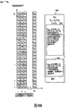
Figure 19 demonstrates a part that is woven into the exemplary downlink Traffic Channel section that comprises first user and second user's modulation symbol.
Figure 20 demonstrates the variant of Figure 19, and it illustrates the layout of first user's non-zero modulation symbol in the section that transmits the first subscriber-coded bit, determines the layout of second user's modulation symbol for this section.
Figure 21 is the diagrammatic sketch of the flow chart of the emission data sets illustrative methods of closing.
Figure 22 is the diagrammatic sketch of the flow chart of example communication method.
Embodiment
Fig. 1 is the diagrammatic sketch of example communication system 100.System 100 comprises equipment and the method that is intended to utilize efficiently the downlink traffic channel air link resources.Example system 100 can be for example to use OFDM (OFDM) multi-address radio communication system of stack signaling in down link.System 100 comprises a plurality of sub-districts (sub-district 1 102, sub-district M 104).Each sub-district (sub-district 1 102, sub-district M 104) is represented the wireless coverage area of corresponding base station (BS 1 106, BS M 108) respectively.A plurality of wireless terminals (WT) (WT 1 110, WT N112, WT 1 ' 114, WT N ' 116) are included in the system 100.At least some WT are mobile node (MN); MN can move in whole system 100.Each WT (110,112,114,116) can set up Radio Link with the BS corresponding to WT present located sub-district.In Fig. 1, (WT 1 110, WT N 112) are connected to BS 1 106 via Radio Link (118,120) respectively; (WT 1 ' 114, WT N ' 116) are connected to BS M 108 via Radio Link (122,124) respectively.
BS (106,108) is connected to network node 126 via network link (128,130) respectively.Network node 126 is connected to other network node via network link 132, for example router, other base station, aaa server node, home agent node etc. and/or internet.Network link 128,130,132 can be an optical fiber link for example.Network node 126 and network link the 128,130, the 132nd, the part of backhaul network, this backhaul network is linked at together and provides connection with the various BS in the different districts, makes the WT that is arranged in a sub-district to communicate by letter with the peer node of different districts.
Fig. 2 is the diagrammatic sketch of exemplary base 200.Exemplary BS 200 is called as access node sometimes.BS 200 can be any BS (106,108) of the system 100 of Fig. 1.Exemplary BS200 comprises receiver 202, transmitter 204, processor 206, I/O interface 208 and the memory 210 that links together via bus 212, and wherein various elements can pass through bus 212 swap datas and information.
I/O interface 208 is connected to other network node with BS 200, for example router, other base station, aaa server node, home agent node and/or internet.I/O interface 208 is for backhaul network provides interface, and this backhaul network provides interconnectivity between the node of different districts.
Down link signal sending module 228 comprises channel quality determination module 232, distributes transmitter module 227 and coding and modulate emission control module 234.Coding and modulate emission module 234 comprise that first user selects module 236, and coding and modulation module X 238, the second users select module 240, and coding and modulation module Y 242.
Down link signal sending module 228 controls transmitter 204 and the operation of coding and modulate emission module 216, comprises the down link signal of downlink traffic section assignment messages 262 and comprises the downlink traffic channel signals of superposed signal with emission.Channel quality determination module 232 is the communication channel quality between each WT that is considered 300 definite base station 200 and the wireless terminal 300 (referring to Fig. 3) for example based on the channel-quality feedback report 258 that receives from WT 300.
The operation of coding and modulate emission module 234 control codings and modulate emission module 216.It is the user that particular downlink Traffic Channel section selects to be assigned to first user that first user selects module 236, and the information that will be delivered to first user is by coding and modulation module X 238 codings and modulation.In certain embodiments, the information bit amount that can transmit at the given downlink traffic channel section that is used for first kind user is less than the information bit amount that can transmit at the same downlink traffic channel section that is used for the second class user.First user selects module 236 to select first kind user according to the amount of information of transmitting on given interval.For example, the first kind user who is generally given section selection can have a spot of user data/information that will receive at current time in down link, if and such user is assigned as the second class user for given Traffic Channel section, some available information bit positions of section will not be required and will be filled for example zero, thus the waste air link resources.Coding and modulation module X 238 comprise modulation selector module 244, controllable type coder module 246, and controllable type qpsk modulator module 248.Modulation selector module 244 receives the designator of the every MTU of bit (BPM) value (Bits per MTU value) or BPM value, for example indicate the data rate indicator value of the number of the frames of information bits that will in section, launch, each frame has the information bit of fixed qty for selected first user, and modulation selector module 244 generates: (i) send to encoding rate designator (CRI) signal of controllable type coder module 246 and (ii) send to the modulation scheme designator (MSI) of controllable type QPSK modulation module 248.The number of encoding rate designator (for example being each section) indication input information bits and the respective coding bit number that produces from the input bit number of indicating.Controllable type coder module 246 receives uncoded message bit stream and encoding rate designator, and two inputs are all corresponding to selected first user.Number (k) the execution block coding of the information bit that receives that 246 pairs of controllable type coder module will be transmitted in section, thereby the number (n) of generation coded-bit.Controllable type encoder 246 is grouped into coded-bit subclass (each bit subset will be transmitted) with bitstream encoded in sub-segments, and send (forward) to controllable type qpsk modulator module 248 before the bit with coding.In certain embodiments, the bit of some codings of sub-segments is corresponding to the symbol energy horizontal pattern (symbol energy level pattern) of sub-segments, and other coded-bit of sub-segments is corresponding to the value of transmitting on the modulation symbol that is generated.In a plurality of nil symbol ratio QPSK modulation schemes of modulation scheme designator (MSI) indication which will be used for the modulating-coding bit.In certain embodiments, each possible nil symbol ratio QPSK modulation scheme is corresponding to the zero MTU fragment (fraction) of different numbers.For example, first modulation scheme can comprise an acyclic homologically trioial system symbol and a non-zero QPSK modulation symbol in each sub-segments, and wherein each sub-segments comprises two MTU; Second modulation scheme can comprise three acyclic homologically trioial system symbols and a non-zero QPSK modulation symbol in each sub-segments, wherein each sub-segments comprises four MTU, and the 3rd modulation scheme can comprise seven acyclic homologically trioial system symbols and a non-zero QPSK modulation symbol in each sub-segments, wherein each sub-segments comprises eight MTU.Some different QSPK nil symbol ratio modulation schemes can have the sub-segments of different numbers in each section.Some different QSPK nil symbol ratio modulation schemes can have the sub-segments of similar number in each section, for example have the non-zero QPSK modulation symbol of different numbers in each sub-segments.Controllable type QPSK modulation module 248 receives the MSI of automodulation selector module 244 and from the coded-bit of controllable type coder module 246, and be each sub-segments generation QPSK modulation symbol set of section, each modulation symbol set comprises at least some acyclic homologically trioial system symbols, and wherein the number of acyclic homologically trioial system symbol is the function of MSI divided by the result of the number gained of the MTU of each sub-segments.The position of non-zero modulation symbol in sub-segments and the value of the non-zero modulation symbol that generated by controllable type qpsk modulator module 248 are transmitted the corresponding coded-bit of information bit with first user.
It is the user that particular downlink Traffic Channel section selects to be assigned to second user that second user selects module 240, and the information that will pass to second user is by coding and modulation module Y242 coding and modulation.It is that the downlink traffic channel section is selected second user from a plurality of potential second users: (i) potential second user's profile information (profile information) according to following information that second user selects module 240, for example channel condition and modulation symbol power level and (ii) before distributed to first user's of same downlink traffic channel section the power level of non-zero QPSK modulation symbol.For example, in the selection course of downlink traffic channel section, second user select module 240 can determine selected first user's non-zero modulation symbol power level with and the ratio of the power level of the modulation symbol that is associated of potential second user, make for acceptable potential second user, this ratio should surpass the predetermined threshold greater than I acceptance threshold, I acceptance threshold expection wherein need make the user that wins should be able to successfully detect first user's modulation signal, for example 3db or 5db surplus (margin).Second user selects module 240 to control with the corresponding not decoded information of second user bit stream and points to coding and modulation module Y 242, and indicates BPM (it is the tolerance of data rate) and will be used for the coding of the second user profile bit stream and the power level of modulation to coding and modulation module Y 242 transmission indicator signal.For example, coding and modulation module Y 242 can support can selecteed a plurality of different pieces of information speed levels, and each data rate is all corresponding with modulation scheme (for example traditional QPSK, QAM16, QAM64, QAM256), encoding rate and the modulation symbol power level that is associated.Coding and modulation module Y 242 comprise coder module 250 and modulator block 252.Coder module 250 becomes the coded-bit set to the information bit collective encoding that for example will transmit in section, the pattern indication code word of coded-bit.Output from coder module 250, it is coded-bit, be sent to modulator block 252, this modulator block 252, is modulated to the bit value of coding on the modulation symbol (for example QAM 16 or QAM 64 or QAM256 modulation symbol) according to selected modulation scheme (for example traditional QPSK, QAM 16, QAM64 or QAM 256) with the power level of appointment.
In certain embodiments, be included in coding and the modulate emission control module 242 various features and or function, can partly or entirely be implemented in encode and modulate emission module 216 in.In Fig. 2, modulation selector module 244, controllable type coder module 246, controllable type qpsk modulator module 248, coder module 250, modulator block 252, and second user selects module 240 to be shown by a dotted line randomly to be included in the down link signal sending module 234; Be not included in such function in the down link signal sending module 234 usually for example with the form of the combination of hardware, software or hardware and software, be included in coding and the modulate emission module 216.Fig. 4 and Fig. 5 provide the exemplary embodiment of at least some functions that comprise that front reference encoder and modulate emission control module 234 described, and coding wherein and modulate emission control module 234 are implemented in the coding and modulate emission module 216 in the transmitter 204.
The operation of uplink signal sending module 230 receiver control 202 and decoder 214 thereof comprises channel quality reporting 258 and reception, the demodulation sign indicating number of the uplink traffic channel message 260 that receives.
Data/information 220 comprises a plurality of WT data/information 254 set (WT 1 data/information 268, WT N data/information 270) and system data/information 256.WT 1 data/information 268 comprises user data 272, WT identifying information 274, device/session/resource information 276, channel quality information 278, the zone field 282 that down-chain resource solicited message 280 and downlink traffic channel section distribute.
User data 272 comprises user data/information, such as the peer node that is derived from WT 1, passes to the data/information of expression voice, text or the video of WT 1 via downlink traffic channel section signal.User data 272 also comprises the user data/information that receives at the uplink traffic channel section from WT 1, gives the peer node that communicates the WT 1 of session with WT 1 before this user data/information is intended to.
The zone field 282 that the downlink traffic channel section distributes comprises information bit 284, section identifying information 286 and coded/modulated information 288.For WT1, can there be the zone field 282 of the DL traffic channel assignments of a plurality of set, for example distribute to the information 282 of the respectively corresponding set of each D.L. Traffic Channel section of WT 1 by scheduler module 226.Information bit 284 comprises the information bit that is input to controllable type coder module 246 or coder module 250.Downlink traffic channel section in the section identifying information 286 identification down link sequential organizations also is categorized as the first kind user or the second class user with WT1.Coded/modulated information 288 comprises modulation type information 290, for example QPSK and nil symbol ratio modulation scheme, traditional QPSK, QAM16, QAM64, QAM256, wherein for first kind user, modulation scheme can comprise the sub-segments size, encoding rate, zero MTU frag info and coded-bit map information.Coded/modulated information 288 also comprises the every MTU 299 of bit, modulation symbol transmission power information 294, coded-bit 296 and modulation symbol information 298.Coded-bit 296 can be the output from controllable type coder module 246 or coder module 250, and modulation symbol information 298 can comprise the value by modulator block 248 or 252 modulation symbols that generate simultaneously.
System data/information 256 comprises uplink/downlink sequential and frequency structure information 207, coded/modulated module X information 209 and coded/modulated module Y information 211.Uplink/downlink sequential and frequency structure information 207 comprise MTU information 213 and downlink traffic channel zone field 215.For example, minimum transmission units (MTU) can be the OFDM subcarrier symbol (tone symbol) that is illustrated in the basic air link resources of using in the ofdm system, for example a corresponding subcarrier of OFDM symbol sequential duration at interval.Downlink traffic channel zone field 215 comprises the information of each downlink traffic channel section in identification down link sequential and the frequency structure (each section of predetermined OFDM subcarrier symbol that for example comprises the appointment of fixed number).Uplink/downlink sequential and frequency structure information 207 also comprise other system configuration information, symbol sequential information for example, subcarrier interval (tone spacing) information, the up link number of subcarriers, the downlink subcarriers number, uplink carrier frequency, downlink carrier frequency, uplink bandwidth, downlink bandwidth, up link sets of subcarriers, downlink subcarriers set, up link subcarrier frequency hopping (hopping) information, up link pause (dwell) information, downlink subcarriers frequency hopping information, uplink service section structure information, the repeatability sequential organization, for example symbol time is grouped into for example pause at interval and with symbol time at interval, the half crack, time slot, overtime crack (superslot), beacon slot, extremely wide time slot (ultra slot) etc.
Coding and modulation X information 209 comprise first user's choice criteria 228, for example by the level of the first subscriber-coded and BPM user's request that the modulation data rate level is supported that is realized.Encoding rate indicator information 219 comprises for example look-up table, it makes the encoding rate indicator value with following relevant: the information bit number, the coded-bit number, information bit is to the map information of employed coded-bit, coded-bit is to the map information of zero/non-zero modulation symbol position, and coded-bit is to the mapping of modulation symbol values.MSI information 221 comprises a relevant information that makes in each modulation scheme indicator value and a plurality of modulation schemes that can be used by controllable type qpsk modulator module 248.Sub-segments information 223 comprises the potential sub-segments size of the identification (information of each the sub-segments position in the information of each sub-segments in) the information for example, 2,4 or 8 MTU of each sub-segments, identification section, identification section.
Coding and modulation module Y information 211 comprise second user's choice criteria 225, coded modulation information 227 and power information 229.Second user's choice criteria 225 comprises by second user selects module 240 employed information in the process of assessing potential second user for the downlink traffic channel section, user's overview evaluation criteria information for example, the data rate horizontal information, with respect to first user's who distributes power ratio threshold level, or the like.Coded/modulated information 227 comprises that each data rate level is corresponding with the encoding rate that comprises information bit number, coded-bit number and modulation symbol type (for example traditional QPSK, QAM 16, QAM 64, QAM 256) about the information of a plurality of data rate levels of being supported by coding and modulation module Y 250.Power information 229 comprises the reference power level that is associated with each data rate level of sign in information 227.
Data/information 220 also comprises the channel quality reporting 258 that receives, the uplink traffic channel message 260 that receives, via the subscriber data message that I/O interface 261 receives, downlink traffic channel section assignment messages 262, potential second user profile 264 and power ratio information 266.The channel quality reporting 258 that receives is for example from the feedback report of WT 300, the downlink channel quality that its indication is for example measured based on the frequency pilot sign that receives and/or the beacon signal that receives.The uplink traffic channel message 260 that receives comprises the user data of the peer node of the WT that is intended to be routed to the transmission of uplink signal.The subscriber data message that receives via I/O interface 261 comprises the user data that receives via backhaul network, and the current use of this user data BS 200 is requested to be transmitted into WT via downlink traffic channel signals as the network connection point of WT.For example, BS 200 can receive N the user data frame that is requested to pass to WT 1 via I/O interface 208; The N that a receives user data frame can be originally generated by the peer node that communicates the WT 1 of session with WT 1.The N that a receives user data frame also can be attended by membership information, for example time validity information (time validity information).Downlink traffic channel section assignment messages 262 is to be generated the assignment messages of transmitting downlink traffic section assignment information.In certain embodiments, section assignment messages 262 also comprises, sends with respect to the superposed signal that occurs in the section, for the section that is distributed, as the first kind user or the second class user's user ID.In certain embodiments, assignment messages is arranged in BS 200 and all known sequential/frequency structure of WT 300, make about this stack, with getting in touch of particular downlink Traffic Channel section and/or user type, be to determine from the position of assignment messages in the sequential/frequency structure of base station that comprises user ID.Potential second user profile 264 comprises user profile information, for example for given downlink traffic channel section, is each channel quality information fetching and handle 278 among a plurality of second users that just are being considered.The first/the second user power comprises and the power ratio information of the corresponding calculating of modulation symbol of potential emission that than information 266 modulation symbol of potential emission can be applied and be used for given downlink traffic channel section.Determining in second user's the process that for given downlink traffic channel section second user selects module 240 that power ratio information 266 and second user's choice criteria 225 are compared.
Fig. 3 is the diagrammatic sketch of example wireless terminal 300.WT 300 can be any WT (110,112,114,116) of the system 100 of Fig. 1.Exemplary WT 300 comprises receiver 302, transmitter 304, processor 306, user I/O device 308 and the memory 310 that links together via bus 312, and various elements can pass through bus 312 swap datas and information.
For given downlink traffic channel section, if WT 300 is assigned with section and is designated as second user of this section, then the superposed signal that arrives of WT demodulate reception is to extract the modulation signal of stronger level, the modulation signal of this stronger level comprises the non-zero qpsk modulation signal that has high relatively power level with respect to second user's modulation signal, with second user's modulation signal as noise processed; Then, WT 300 from primary reception to superposed signal extract the QPSK modulation symbol of demodulation, and the remaining signal of demodulation sign indicating number, for example lower power levels QPSK signal or QAM signal, thereby obtain the estimation of the second user profile bit.This is a kind of mode than weak signal that decoding is superposeed.
The interchangeable coding/decoding method that some embodiment that the advantage of modulation and encoding scheme partly comes leisure to be used for second user use.The introducing of nil symbol is convenient to realize that novel coding/decoding method makes coding/decoding method have robustness for channel estimation errors simultaneously.The signal that the receiver decodable code is more weak and decoding and deduct stronger signal from the signal that receives.For example, if receiver has detection and wipes the ability of comparing very large signal with the predetermined nominal value, receiver can decode second than weak signal so, and except strong signal shows as second situation about disturbing than the spike in the emission of weak signal, even need not to know the existence of strong signal.
User I/O device 308 comprises, for example microphone, loud speaker, auxiliary keyboard, keyboard, mouse, touch-screen, video camera, display, siren, vibrating device etc.Various user I/O devices 308 are used to import the user data/information of the peer node that is intended to be used for WT 300, and data/information of receiving from the peer node of WT 300 of output.In addition, user I/O device 308 is used to start various functions by the operator of WT 300, for example powers on, descends electricity, calling (place a call), end call (terminate a call) etc. are set.
Down link signal sending module 326 comprises channel quality determination module 330 and decoding reconciliation regulation and control molding piece 332.Channel quality determination module 330 is handled downlink pilot signal and/or the beacon signal that receives and is generated channel quality reporting 394.Decoding is conciliate regulation and control molding piece 332 and is comprised first line module 334 and second line module 336.The downlink traffic channel signals of the stack that the operation of first line module 334 control demodulator/decoder 314 receives with processing is also extracted the first user profile bit.First line module 334 comprises energy detection module 338, modulation symbol processing module 340, sub-segments decoder module 342 and section piece decoder module 343.In certain embodiments, one or more modules 338,340,342 and 343 various combinations can be embodied as individual module, and this individual module is for example carried out sub-segments and section decode operation as the joint operation that is used for corresponding to the given encoding block of section.Energy detection module 338 is handled the corresponding received signal of downlink traffic channel section that has been assigned to its first user with WT 300, with definite signal which receives (for example, according to MTU, the OFDM subcarrier symbol in the section) be the high relatively signal of energy.Second user's modulation signal of stack, for example traditional Q PSK or the QAM signal that power level is lower than non-zero first user's qpsk modulation signal is used as noise processed.First user's modulation signal comprises some acyclic homologically trioial system symbols at least in each sub-segments.In the MTU that receives that comprises 0 first user's modulation signal and non-zero second user's modulation signal, energy detection module 338 should be categorized as acyclic homologically trioial system signal with MTU from first user's angle.The bit value of coding is transmitted in the position of the signal that each sub-segments internal power of section is high relatively.Then, the modulation symbol that the power of being located is high relatively, the QPSK modulation symbol is handled to obtain extra encoding ratio paricular value by modulation symbol processing module 340.Sub-segments decoder module 342 is for example via look-up table, the determined value of non-zero first user's modulation symbol of receiving is converted to coded-bit, and the positional information about the non-zero modulation symbol that will determine is converted to extra coded-bit.Sub-segments decoder module 342 will be combined as the coded-bit set of sub-segments corresponding to position coded-bit of determining and the coded-bit of determining corresponding to value.Sub-segments decoder module 342 will be given section piece decoder module 343 before the sub-segments coded-bit corresponding to each sub-segments of section.Section piece decoder module 343 will be combined in the section set from the coded-bit set of each sub-segments of given section, and 343 pairs of coded-bits of section piece decoder module are decoded with the set of the information bit that obtains to recover.
The stack downlink traffic channel signals that the operation of second line module 336 control demodulator/decoder 314 receives with processing is also extracted the second user profile bit.Second line module 336 comprises that first subscriber signal removes module 344, modulation symbol processing module 346 and section piece decoder module 348.First subscriber signal removes module 344 and uses energy detection module 338 and first user's modulation signal processing module 340 to obtain the estimated value of the position (for example MTU in the section) and the first user QPSK signal, deducts first user's estimated signal of estimation then from the complex superposition signal that receives.The signal of gained is before given modulation signal processing module 346.The signal that modulation signal processing module 346 receives corresponding to the MTU of section, for example with the MTU that comprises first user's non-zero modulation symbol corresponding from module 344 the adjusted signal and with the corresponding signal of not adjusting of the MTU that is defined as first user's acyclic homologically trioial system character position.The operation of modulation symbol processing module 346 control demodulators is with demodulation second user's traditional Q PSK or QAM signal, for example QAM 16 or QAM 64 or QAM 256 modulation symbols, thus be each demodulation symbol acquisition coded-bit.Section piece decoder module 348 receives from the coded-bit of module 346 outputs and controls decoder passes to second user section with decoding and recovery information bit.
It should be noted that first and second users distribute and the indication appointment of use with respect to each downlink traffic channel section.Usually, first and second users will be corresponding to different WT.Be designated as first user's WT for a downlink traffic channel section, for example depend on current resource needs, may be designated as second user for different downlink traffic channel sections.In certain embodiments, for given downlink traffic channel section, WT300 can be first user and second user of same downlink traffic channel section, thereby receive the information bit that transmits with relative high power level via first user modulation and coding (QPSK that for example has some nil symbols) with low BPM speed, and receive the information bit of the higher number that transmits with relative low power level via second user modulation and coding (for example traditional Q PSK, QAM 16 or QAM64 or QAM 256) with high BPM speed than low number.
Uplink signal sending module 328 controls transmitter 304 and the operation of encoder 316, and to BS 200, described uplink signal comprises channel quality reporting 394 and uplink traffic channel section message 396 with coding, modulation and transmission of uplink signal.Uplink traffic channel section message 396 can comprise and sends to the user data of peer node that communicates the WT 300 of session with WT 300.Such uplink traffic channel message 396 can be regarded as the down-chain resource request message by BS 200, and wherein this BS 200 is used as its network connection point by peer node.
Data/information 320 comprises WT data/information 350, system data/information 352, channel quality reporting 394, uplink channel message 396, down link section assignment messages 398 that receives and the downlink traffic channel signals information 399 that receives.
WT data/information 350 comprises user data 354, and WT identifies (ID) information 356, base station IDs information 358, device/session/resource information 360, the zone field 364 that channel quality information 362 and downlink traffic channel section distribute.User data 354 comprises the data/information of peer node that is intended to be used for communicate with WT 300 WT 300 of session, and this data/information is intended to be transmitted into BS 200 by the uplink traffic channel section by WT 300.User data 354 also comprises being derived from WT 300 and communicates the peer node of WT 300 of session and the data/information that receives from BS 200 via downlink traffic channel section message 399.
Wireless terminal identification information 356 comprises, for example WT IP address and the BS 200 WT active user identifier of distributing.Base station identifiers information 358 comprises identifier, for example distinguishes the value of WT 300 as particular B S 200 network connection points of its current network tie point in a plurality of different BS network connection points from wireless communication system.In certain embodiments, BS id information 358 comprises the information of identification particular sector and/or the employed carrier frequency of BS network connection point.Device/session/resource information 360 comprises up link and down link section (for example distributing to the Traffic Channel section of WT300), and comprises about communicating the address of peer node of WT300 of session and the session information of routing iinformation with WT 300.Channel quality information 362 comprises the information about the radio communication channel between WT 300 and the BS 200 measurement, that derive and/or that estimate.Channel quality information 362 can comprise, for example measure, derive based on pilot tone that receives and/or beacon downlink signals and/or estimated signals noise ratio and/or signal-to-jamming ratio information.
The zone field 364 that downlink traffic channel distributes comprises section identification information 366, the first/the second user totem information 368, coded/modulated information 370 and the information bit 372 that recovers.Section identification information 366 comprises the information of the downlink traffic channel section of the distribution in identification down link sequential/frequency structure.The first/the second user totem information 368 comprises identification for the downlink traffic channel section that distributes, and whether WT 300 has been designated as first user or second user's information.Coded/modulated information 370 comprises modulation type information 374, BPM information 376, power information 378, coded-bit 380 and modulation symbol information 382.Modulation type information 374 for example comprises modulation scheme designator and the encoding rate indicator value for first kind user.Modulation type information 374 for example comprises the information for the second class user's appointment QPSK, QAM16 or QAM64 or QAM256.The every MTU of bit (BTM) the 376th is used for the information data rate of the first or second class user's section.Power information 378 is included in the power level of measuring on the modulation signal that receives, and the power level difference between definite signal that receives and being used to is discerned the power margin information of the signal that transmits the non-zero modulation that is intended to be used for first user.Coded-bit 380 is coded-bits that first or second user that discerned for information 368 from the downlink traffic channel symbol of the section that receives recovers.For first kind user, coded-bit 380 can be incorporated on the basis of each section and be grouped into single being grouped into subclass on the basis of each sub-segments, and simultaneously for the second class user, coded-bit 380 can be grouped into single of section.Modulation symbol information 382 comprises which MTU is in the information of transmitting the non-zero first user QSPK modulation symbol in identification section and/or the sub-segments.Modulation symbol information 382 also comprises the information of the estimated value of the modulation symbol that receives that identification is processed.The information bit 372 that recovers comprises WT behind the demodulation code operations, to pass to the estimation as the information bit of first user or second user's WT 300 in section.The downlink traffic channel section assignment information 364 that can have a plurality of set, for example distribute to the downlink traffic channel section assignment information 364 of all corresponding set of each downlink traffic channel section of WT 300, send according to superposed signal, each distributes corresponding with downlink traffic channel section and corresponding user type appointment.
System data/information 352 comprises the identification information 383 of base station, uplink/downlink sequential and frequency structure information 384, the first user's demodulate/decode information 386 and second user's demodulate/decode information 388.Base station IDs information 383 is for example based on sub-district, sector and/or employed carrier frequency, comprise with system in the corresponding a plurality of different base station identifiers of different B S network connection point.Uplink/downlink sequential and frequency structure information 384 comprise MTU information 390 and downlink traffic channel zone field 392.For example, minimum transmission units (MTU) can be the OFDM subcarrier symbol of the basic air link resources used in the ofdm system of expression, for example a corresponding subcarrier of OFDM symbol sequential duration at interval.Downlink traffic channel zone field 392 comprises the information of each downlink traffic channel section in identification down link sequential and the frequency structure (each section of predetermined OFDM subcarrier symbol that for example comprises the appointment of fixed number).Uplink/downlink sequential and frequency structure information 384 also comprise other system configuration information, symbol sequential information for example, subcarrier interval information, the up link number of subcarriers, the downlink subcarriers number, uplink carrier frequency, downlink carrier frequency, uplink bandwidth, downlink bandwidth, up link sets of subcarriers, downlink subcarriers set, up link subcarrier frequency hopping information, up link pause information, downlink subcarriers frequency hopping information, uplink service section structure information, the repeatability sequential organization, for example symbol time is grouped into for example pause at interval and with symbol time at interval, the half crack, time slot, overtime crack, beacon slot, wide time slot etc. extremely.
The UL/DL sequential of different sets and frequency structure information 384 can exist and be stored in wireless communication system in different B S 200 corresponding WT 300 in.
First user's demodulation sign indicating number information 386 comprises and can be selected to gather with each coding and the modulation option information corresponding of transmitting first user's downlink traffic channel signals by base station 200.For example, ensemble of communication can comprise the first user data rate level value, the BPM value, the encoding rate designator, the modulation scheme designator, the sub-segments dimension information, the information of the signal that the demodulation sign indicating number is received (for example being used for determining the power level threshold value of the position of non-zero qpsk modulation signal), and decoded information (for example the value of determined positional information and/or definite QPSK signal being converted to the look-up table of coded-bit and/or information bit).For example discerned the WT 300 that it is designated as first user of downlink traffic channel section and has discerned the first user data rate level, discerned and visited the ensemble of communication in first user's demodulate/decode information 386 by handling the down link section assignment messages that is received.The accessed ensemble of communication that comes self information 386 is used in the process of the signal that processing receives by first line module 334, thereby produces the information bit 372 that recovers.
Second user's demodulation sign indicating number information 388 comprises and can be selected to gather with each decoding and the modulation option information corresponding of transmitting second user's downlink traffic channel signals by base station 200.For example, ensemble of communication can comprise the second user data rate level value, the BPM value, encoding rate information (the information bit number in the section for example, coded-bit number in the section, code word size), modulation type designator (for example indicating QPSK or QAM16 or QAM64 or QAM256), the information (for example power level information) of the signal that demodulate reception arrives will be used to, obtain soft value (soft value), and decoded information (the soft value that for example will determine is converted to the code information of the information bit of recovery).For example discerned the WT 300 that it is designated as second user of downlink traffic channel section and has discerned the second user data rate level, discerned and visited the ensemble of communication in second user's demodulate/decode information 388 by handling the down link section assignment messages that is received.The accessed ensemble of communication that comes self information 388 is used in the process of the signal that processing receives by second line module 336, thereby produces the information bit 372 that recovers.In certain embodiments, second user of appointment also receives and handles some assignment information corresponding to first user that are used for same downlink traffic channel section, for example discerns the information of the first user data rate level; Such information was used when removing the first user QPSK superposition modulated symbol before the demodulation sign indicating number second user QAM signal.In certain embodiments, the power level difference that the first user QPSK signal and second user superpose between the QAM signal is enough to wittingly make that WT should be able to discern the MTU that comprises non-zero QKSK first user's modulation signal, and need not decoding or assess first user's ratio levels information.
Channel quality reporting 394 by channel quality determination module 330 for example based on to the measurement of the downlink pilot signal that receives and/or beacon signal and generate.Channel quality reporting 394 is transmitted into BS 200 by WT 300 and is used for assessing into the downlink traffic channel section candidate's second user.
Uplink traffic channel message 396 transmission is intended to be used for the user data of the peer node of WT 300.Uplink traffic channel message 396 is transmitted into BS 200 by the uplink traffic channel section, and this BS 200 is used as its network connection point by WT 300.User data is for example before given BS 200 via backhaul network, and as its network connection point, the user data that receives in this case is regarded as the request to the downlink traffic channel resource to this BS 200 by the peer node of WT 300.The downlink traffic channel section assignment messages 398 that receives is the distribution of specific downlink traffic channel section being distributed to WT 300 that receive.The downlink traffic channel section assignment messages 398 that receives can comprise the information (for example section index identifier (segment index identifier)) of the section that identification distributes, the user (for example WTID) who distributes, the user type of section (for example first kind or second type), and/or the information of recognition data speed level.The downlink traffic channel signals information 399 that receives comprises the information that is included in the downlink traffic channel signals (downlink traffic channel signals of the stack that for example receives) that receives or therefrom determines.
Fig. 4 is connected to the exemplary coding of transmitting antenna 404 and the diagrammatic sketch 400 of modulate emission module 402.Exemplary coding and modulate emission module 402 can be the exemplary embodiments of module 216 of the BS 200 of Fig. 2, and antenna 404 can be the antenna 205 of Fig. 2 simultaneously.Exemplary coding and modulate emission module 402 comprise coding and modulation module X 406, coding and modulation module Y 408, composite module 410, composite signal transmitter module 412, second user selects module 414, the second user's Multiplexing modules 416, user's profile information 418, transmit power control module 415, and sector division information/module 417.Suppose that for given downlink traffic channel section first user is selected by another module in the BS (for example first user of the BS 200 of Fig. 2 selects module 236).First user of downlink traffic channel section is selected with emission in section with respect to second user's of same section low BPM by BS.In many examples, coding and the highest BPM ratio supported of modulation module X 406 are less than the minimum BPM ratio of encoding and modulation module Y 408 is supported.For comprising modulation symbol X (S
X) 430 and modulation symbol Y (S
Y) 431 given downlink traffic channel section, non-zero modulation symbol X (S
X) the 430th, QSPK, and power level is higher than non-zero modulation symbol Y (S
Y) 431, they are QAM (for example QAM16 or QAM64 or QAM256) normally.In certain embodiments, coding and modulation symbol Y 408 comprise the QPSK ability.
Coding and modulation module X 406 comprise modulation selector module 420, controllable type encoder 422 and controllable type qpsk modulator 424.First user that coding and modulation module X 406 receptions are selected is coded-bit (UB not
X) 426 and signal 428, signal 428 transmits the designator of corresponding requested BPM (the every MTU of bit) data rates or user's data speed.Coded-bit (UB not
X) 428 be imported into controllable type encoder 422, and BPM signal 428 is imported into modulation selector module 420.Modulation selector module 420 selects encoding rate and modulation scheme with the function as BPM 428; The control signal of modulation selector 420 is sent to controllable type encoder 422 and controllable type qpsk modulator module 424.Encoder 422 is handled the information bit set (for example 1,2 or 3 frames of information bits) corresponding to requested BPM, with the not coded bit stream (UB that receives that specifies number
X) 426 bits of encoded are the block encoding set of coded-bit, and be subclass with the packet of code bits of section, the subclass of each coded-bit is corresponding to the sub-segments of same downlink traffic channel section.The operation of encoder 422 is to carry out according to the control signal that receives of order.Modulator 424 is controlled to generate into each sub-segments the mixing of acyclic homologically trioial system symbol and non-zero QPSK modulation symbol, some coded-bit information are transmitted in the position of nonzero sum acyclic homologically trioial system symbol in sub-segments, and the value of non-zero modulation symbol is transmitted some coded-bit information.Output modulation symbol X (S
X) 430 from qpsk modulator 424 output and be routed to composite module 410.In addition, the power level signal P that is associated with non-zero QPSK modulation symbol
X432, export and be imported into second user from coding and modulation module X 406 and select module 414.
Potential candidate second user of downlink traffic channel section is by identification of base stations, and id signal (potential second user 1 434, potential second user 2 436 ..., the potential second user N438) before given second user and selected module 414.Each potential second user (potential second user 1 434, potential second user 2 436 ..., the potential second user N 438) have accordingly a not coded bit stream (UB
1Y440, UB
2Y442 ..., UB
NY444), it can be used as the input of second user's Multiplexing module 416.Second user selects module 414 to receive the power level P of first user's modulation symbol
X432, and with regard to potential second user (434,436,438) whether be acceptable to potential second user (434,436,438) test, from the set that can accept second user, select selected second user then, and in the signal 448 that sends to second user's Multiplexing module 416, send this selection.As the part of selection course, second user selects module 414 to send the profile information memory 418 of request signal 450 (for example comprising the potential second user ID designator, as WT ID) to the user.In certain embodiments, user profile information 418 can be arranged in BS memory 210.Can comprise that corresponding to the set of potential second user's profile information subscriber channel condition for example is about the data rate and the corresponding modulation symbol power level (P that can be supported by WT of downlink traffic channel signals
Y).User profile information sends to second user via signal 452 and selects module 414.Second user selects module 414 can comprise SNR
THRESHHOLD454, SNR
THRESHHOLDThe power ratio level that 454 expressions should surpass for being considered to acceptable candidate second user.For given potential second user, second user selects module 414 to determine first user's modulation symbol power level P
XDivided by the horizontal P of potential second user power
YRatio (the P of gained
X/ P
Y), P here
X/ P
YValue should be greater than the SNR that is considered to acceptable potential second user
THRESHHOLD454.With SNR
THRESHHOLDValue 454 is chosen to accept SNR (for example representing the 3db or 5db surplus) greater than the I of the required expection of X modulation signal of successfully decoding.As the result of selection course, second user selects module 414 to select selected second user, and it is delivered to second user's Multiplexing module 414 in signal 448; Control signal corresponding 456 selects module 414 to send to coding and modulation module Y 408 from second user, for example transmit selected data rate level, selected data rate level identification BPM, modulation type (QPSK for example, QAM16 or QAM64 or QAM256), encoding rate and relevant modulation signal power level P
Y
Second user's Multiplexing module 416 receives second user selection signal 448, send and the corresponding not coded-bit of selected second user data stream (UB before these second user selection signal, 448 control multiplexers 416
1Y440, UB
2Y442 ..., UB
NY444) in selected one.The not decoded bits Y (UB that selects
SY) 458 from the output of second user's Multiplexing module 416 and be input to coding and modulation module Y 408.Coding and modulation module Y 408 (for example supporting QPSK, QAM16, QAM64 and QAM256) comprise encoder 460 and modulator 462.Encoder 460 receives the noncoded information bit stream (UB of selected input
SY) 458 and be section execution block coding according to the selected encoding rates that control signal 456 is determined.The coded-bit that encoder 460 generates is before given modulator 462, here the modulation type of determining according to control signal 456 is selected, coded-bit is mapped to QPSK or qam signal, for example QAM16 modulation symbol or QAM64 modulation symbol or QAM256 modulation symbol.In other embodiments, coding and modulation module Y 408 can support the combination of other modulation type and/or different modulating type.
Modulation symbol Y (S
Y) 431 export and be input to composite module 410 from coding and modulation module Y 408.Composite module 410 comprises adder Module 411, perforation (punch) module 413, and transformation of scale (scaling) module 419.In certain embodiments, composite module 410 comprises in adder Module 411 and the puncture module 413 and does not comprise another.When using adder 411, adder Module 411 is carried out modulation symbol X (S
X) and modulation symbol Y (S
Y) stack, and composite signal 464 is from composite module 464 output, its expression modulation symbol S
XWith modulation symbol S
YStack.When using puncture module 413, puncture module 413 is from modulation symbol X (S
X) modulation symbol be non-zero and will occupy the same subcarrier symbol time, from having (S from modulation symbol X
X) the modulation symbol Y (S of corresponding non-zero modulation symbol
Y) middle punch falls a modulation symbol.In this case, composite signal 464 expressions also do not have the modulation symbol Y (S of perforation
Y) 431 and from modulation symbol X (S
X) combination of 430 non-zero modulation symbol.Composite signal 464 is imported into composite signal transmitter module 412 (for example comprising amplifier stage), and outputs to antenna 404, and by this antenna 404, the downlink traffic channel signals of combination is launched into WT.
According to the power level information that is associated with non-zero X modulation symbol and Y modulation symbol, the transformation of scale module 419 applied power transformations of scale that are connected to transmit power control module 415 are to the modulation symbol that is combined.Transmit power control module 415 receives related with X and Y non-zero modulation symbol respectively input P
XAnd P
Y, and use the information receive to control to be used to the transmit power level of transmitting the non-zero modulation symbol of first data acquisition system and being used to transmit the modulation symbol of second data acquisition system, to keep the least work rate variance.
It is a plurality of sub-segments that sector division information/module 417 is used for the downlink channel sector division, and a plurality of sub-segments of cutting apart are used by coding and modulation module X 406.Some exemplary differences that Figure 11 illustrates exemplary downlink Traffic Channel section are cut apart.
Fig. 5 is the diagrammatic sketch of exemplary coding and modulation module 500.Exemplary coding and modulation module 500 can be the exemplary embodiments of coding and the modulation module X 406 of Fig. 4.Coding and modulation module X 500 comprise modulation selector module 502, controllable type coder module 504 and may command qpsk modulator module 506; Module (502,504,506) can correspond respectively to the module (420,422,424) of Fig. 4.Modulation selector 502 receives the every MTU of bit (BPM) value or BPM indicator value, such as indication will the information bit that (via the input signal 508 of the required data rate of the selected user of indicating downlink link traffic channel section) transmits in section the data-rate value of frame number.Select coding and modulation option a plurality of codings that modulation selector 502 is supported from module 500 and the modulation option, make and select coding and modulation option to support required BPM ratio and satisfy predetermined nil symbol ratio criteria.In certain embodiments, this selection is carried out via look-up table or similar logic, and this logic can be mapped to encoding rate indicator value and modulation scheme indicator value via the possible data rate that signal 508 transmits with each.The nil symbol ratio is on the basis of each sub-segments, and the number of the acyclic homologically trioial system symbol of appointment is divided by the result of the number gained of the position that can be used to transmit modulation symbol.For example, in one exemplary embodiment, the standard below this select to satisfy: if (i) BPM≤1.5, ZSR 〉=0.125 so, if (ii) BPM≤(1), if ZSR 〉=0.25 so is (iii) BPM≤(1/2), ZSR 〉=0.5 so, if (iv) BPM≤(1/3), ZSR 〉=0.75 so, (if v) BPM≤(1/6), ZSR 〉=0.875 so.A plurality of selections can be satisfied this standard.For example, if BPM=1/3, ZSR can be selected as 0.75 but not surpass 0.875.In certain embodiments, modulation selector 502 selection codings and modulation option, this coding and modulation option satisfy specified standard and are this section generation minimized number non-zero QPSK modulation symbol.This selects to produce encoding rate designator (CRI), and it is from 502 outputs of modulation selector and be input to controllable type encoder 504.This selection also produces modulation scheme designator (MSI) 512, and it is from 502 outputs of modulation selector and be input to controllable type qpsk modulator 506.The number of CRI 510 indication input information bits and the corresponding encoded bit number that will produce from the number of the input information bits of indication.Controllable type encoder 504 comprises CRI related information 514, for example look-up table.It is the uncoded information bit of first number that given CRI value determines to be treated to for section the second number coding bit that CRI related information 514 allows decoder.The encoding rate indicator information also allows decoder to determine sub-segments size and set of coded bits.CRI 510 also can be in controllable type encoder indication section the number of sub-segments, with the coding definition of using for the coded-bit of each sub-segments, the for example location association of the symbol of which coded-bit and non-zero QPSK modulation symbol or sub-segments, and which coded-bit is related with the value of the non-zero QPSK modulation symbol of sub-segments.Noncoded information bit stream (UB
X) 516 handle by controllable type encoder 504, controllable type encoder 504 is input to the coded-bit (CB of controllable type qpsk modulator 506
X) 518.According to various embodiment, some modulation symbols of each sub-segments are distributed into by controllable type qpsk modulator 506 and have modulation symbol values 0 at least.In a plurality of QPSK modulation schemes of MSI 512 indication which is used to the modulating-coding bit.In certain embodiments, each possible QPSK modulation scheme is corresponding to the zero MTU fragment of different numbers.Controllable type qpsk modulator 506 output modulation symbol S
X520, coded-bit that transmits by the position of zero-sum non-zero modulation symbol in the sub-segments and the value of on each non-zero QPSK modulation symbol, transmitting.In addition, controllable type qpsk modulator 506 is also exported energy level output indicator (P
X) 522, P
XBe the tolerance of the power level of non-zero QPSK modulation symbol.P
X522 value selects module 414 to be used for determining the second suitable user by second user, its downlink traffic channel signals will be used identical air link resources transmission as superposed signal, the power level of secondary signal fully is lower than the power level of first subscriber signal, detects first user's down link signal to allow first user.
Controllable type qpsk modulator 506 comprises position determination module 507 and phase place determination module 509.Position determination module 507 determines which output modulation symbol will be that acyclic homologically trioial system symbol and which will be non-acyclic homologically trioial system symbols, the layout of the zero-sum non-zero modulation symbol of transmission coded-bit information.Phase place determination module 509 is determined the phase place of the non-zero modulation symbols that will export, transmits the phase place of the non-zero QPSK modulation symbol of extra coded information bits.
Fig. 6 comprises the diagrammatic sketch and the table of the exemplary embodiment that sub-segments structure, modulation symbol and data-rate information are shown.The information of Fig. 6 can be applied to exemplary coding and the modulation module X 500 of Fig. 5.Diagrammatic sketch 602 illustrates exemplary QPSK modulation symbol and has four kinds of possibilities; Therefore each non-zero qpsk modulation signal of coding and modulation module X 500 generations can pass through 2 information bits of phase place transmission of the complex value of modulation symbol.
Row 604 illustrate 5 exemplary embodiments that can be used for sub-segments coding and modulation.MTU in the QPSK modulation symbol with energy that legend 606 sign sub-segments are distributed is designated as rectangle 608 by cross-hatched, and the MTU in the acyclic homologically trioial system symbol of sub-segments distribution simultaneously is indicated as unblanketed rectangle 610.Each MTU can be, OFDM subcarrier symbol for example, and it is the elementary cell that can be used to transmit the air link resources of a QPSK modulation symbol.
First example 612 illustrates the example of an embodiment, and wherein each sub-segments comprises two MTU unit, and a MTU is assigned with the QPSK modulation symbol with energy, and another MTU is assigned with acyclic homologically trioial system symbol.There are two possible options position with modulation symbol of energy; Therefore, 1 coded-bit can be transmitted by the position of the modulation symbol with energy.In addition, the phase place of complex value with QPSK modulation symbol of energy is transmitted two coded-bits.Per 2 MTU of the coding of first example 612 and modulation scheme transmit 3 coded-bits or maximum BPM=1.5 (supposition encoding rate=1).The also available non-zero symbol ratio of first example 612 (ZSR) is described, wherein the total number of the number of ZSR=acyclic homologically trioial system symbol/sub-segments internal modulation symbol time slot.For example 612, ZSR=0.5.
Second example 614 illustrates the example of such embodiment, and wherein each sub-segments comprises four MTU unit, and MTU is assigned with to have the QPSK modulation symbol of energy, and other three MTU are assigned with acyclic homologically trioial system symbol simultaneously.There are 4 possible options position with modulation symbol of energy; Therefore, transmit the position of the modulation symbol that 2 coded-bits can be by having energy.In addition, the phase place of complex value with QPSK modulation symbol of energy is transmitted 2 coded-bits.Per 4 MTU of the coding of second example 614 and modulation scheme transmit 4 coded-bits or maximum BPM=1.0 (supposition encoding rate=1).For second example 614, ZSR=0.75.
The 3rd example 616 illustrates the example of such embodiment, and wherein each sub-segments comprises eight MTU unit, and 7 MTU divide and be equipped with the QPSK modulation symbol with energy, and another MTU is assigned with acyclic homologically trioial system symbol simultaneously.There are 8 possible options position for the modulation symbol set with energy; Therefore, transmit the position of the modulation symbol that 3 coded-bits can be by having energy.In addition, for each non-zero QPSK modulation symbol of 14 coded-bits of expression, the phase place of complex value with QPSK modulation symbol of energy is transmitted 2 coded-bits.Per 8 MTU of the coding of the 3rd example 616 and modulation scheme transmit 17 coded-bits or maximum BPM=2.125 (supposition encoding rate=1).For the 3rd example 616, ZSR=0.125.
The 4th example 618 illustrates the example of such embodiment, and wherein each sub-segments comprises four MTU unit, and three MTU divide and be equipped with the QPSK modulation symbol with energy, and another MTU is assigned with acyclic homologically trioial system symbol simultaneously.There are 4 possible options position for the modulation symbol set with energy; Therefore, 2 coded-bits can transmit by the position that the modulation symbol with energy is gathered.In addition, for each non-zero QPSK modulation symbol of 6 coded-bits of expression, the phase place of complex value with QPSK modulation symbol of energy is transmitted 2 coded-bits.Per 4 MTU of the coding of the 4th example 618 and modulation scheme transmit 8 coded-bits or maximum BPM=2.0 (supposition encoding rate=1).For the 4th example 618, ZSR=0.25.
The 5th example 620 illustrates the example of such embodiment, and wherein each sub-segments comprises eight MTU unit, and MTU divides and be equipped with the QPSK modulation symbol with energy, and seven MTU are assigned with acyclic homologically trioial system symbol in addition simultaneously.There are 8 possible options position for the modulation symbol with energy; Therefore, transmit the position of the modulation symbol that 3 coded-bits can be by having energy.In addition, the phase place of complex value with QPSK modulation symbol of energy is transmitted 2 coded-bits.Per 8 MTU of the coding of the 5th example 620 and modulation scheme transmit 5 coded-bits or maximum BPM=0.625 (supposition encoding rate=1).For the 5th example 620, ZSR=0.875.
Should be noted that the first, second, third, fourth and the 5th example (612,614,616,618,620) is encoded to energy position with code bit efficiently, because optionally the number of energy position is positive integer value=2
N, wherein N is a positive integer.In certain embodiments, the number of the non-zero QPSK modulation symbol of chooser section size and each sub-segments, make and realize that each sub-segments comprises the coding of at least some acyclic homologically trioial system symbols and QPSK coding and employed each coding of modulation module and the modulation scheme of modulation scheme, possible number=2 of the optional energy position that has
N, wherein N is a positive integer.
Fig. 7 is a table 700, and it has been summed up with reference to the coding of figure 6 descriptions and the exemplary embodiment of modulation scheme.The information that first row 718 is described in the every row that are included in table.First row 702 comprise first example user's disposition shape, and wherein situation (1,2,3,4,5) corresponds respectively to the exemplary embodiment (612,614,616,618,620) of Fig. 6.Row (720,722,724,726,728) corresponds respectively to example scenario (1,2,3,4,5).Secondary series 704 comprises the number of minimum transmission units in the sub-segments (MTU), and it is (2,4,8,4,8) that correspond respectively to situation (1,2,3,4,5).The 3rd row 706 comprise the number of non-zero QPSK modulation symbol in the sub-segments, and it is (1,1,7,3,1) that corresponds respectively to situation (1,2,3,4,5).The 4th row 708 comprise nil symbol ratio (ZSR), and it is (0.5,0.75,0.125,0.25,0.875) that corresponds respectively to situation (1,2,3,4,5).The 5th row 710 are included in the sub-segments number by the coded-bit that transmits with respect to the position of the non-zero modulation symbol set of the position of the assemble of symbol of the acyclic homologically trioial system in the sub-segments, and it is (1,2,3,2,3) that correspond respectively to situation (1,2,3,4,5).The 6th row 712 are included in the number of the coded-bit that transmits by the phase place of non-zero modulation symbol in the sub-segments in the sub-segments, and it is (2,2,14,6,2) that correspond respectively to situation (1,2,3,4,5).The 7th row 714 are included in the number of the coded-bit that transmits in the sub-segments, and it is (3,4,17,8,5) that correspond respectively to situation (1,2,3,4,5).The 8th row 716 are included in the every minimum transmission units of information bit (BPM) of the maximum number that transmits in the sub-segments, if encoding rate=1, it is (1.5,1.0,2.125,2.0,0.625) that corresponds respectively to situation (1,2,3,4,5).Usually, encoding rate is the value less than 1, and therefore BPM correspondingly reduces.Row 717 are included to be used for the comparison purpose, and row 717 comprise that use has the number of potential coded-bit of the standard QPSK of non-zero QPSK modulation symbol in each MTU of sub-segments, the number of potential coded-bit (n) is based on the sub-segments size, and each the modulation symbol time slot that can be sub-segments here transmits 2 coded-bits.The QPSK that the sub-segments of row 717 indication (2,4,8,4,8) individual MTU can use every MTU to have a QPSK modulation symbol transmits (4,8,16,8,16) individual coded-bit respectively.
Fig. 8 comprises table 800 and table 850, and table 800 is listed the first exemplary user and modulated the selector standard, and table 850 illustrates that exemplary wireless terminal data speed needs and can selecteed option.Table 800 comprises first row of listing BPM standard 802 and the secondary series 804 of listing the ZSR standard.If the BPM of first row, 806 indication requests is less than or equal to 1.5, the ZSR of so selected coding and modulation scheme should be more than or equal to 0.125.If the BPM of second row, 808 indication requests is less than or equal to 1, the ZSR of so selected coding and modulation scheme should be more than or equal to 0.25.If the BPM of the third line 810 indication requests is less than or equal to (1/2), the ZSR of so selected coding and modulation scheme should be more than or equal to 0.5.If the BPM of fourth line 812 indication requests is less than or equal to (1/3), the ZSR of so selected coding and modulation scheme should be more than or equal to 0.75.If the BPM of fifth line 814 indication requests is less than or equal to (1/6), the ZSR of so selected coding and modulation scheme should be more than or equal to 0.875.
Table 850 comprises: first row 852, its list exemplary WT (A, B, C, D); Secondary series 854, it comprises the exemplary BPM request (for example for given downlink traffic channel section) of WT; And the 3rd row 856, it comprises the supported option in supposition encoding rate=1 and based on the selection of the standard of table 800, for example the example scenario (1,2,3,4,5) of which appointment of describing with reference to figure 5 and Fig. 6 can be considered to the possibility of modulation scheme.Usually, encoding rate will be selected as less than 1 on the occasion of, and the BPM that is therefore supported will correspondingly reduce.
The request of first row, 858 indication 1.1BPM is to make for the needs of WT A.Selected coding of table 800 indication and modulation situation should have 0.125 or bigger ZSR.Each situation of table 700 indication (1,2,3,4,5) has 0.125 or bigger ZSR; Yet situation 2 is the support information data throughout not, because its maximum BPM=1.0 is less than 1.1 the BPM that is asked; Therefore, from the option of considering, remove situation 2.In addition, situation 5 is the support information data throughout not, because its maximum BPM=0.625 is less than 1.1 the BPM that is asked; Therefore, from the option of considering, remove situation 5.Therefore, arbitrarily situation option (1,3,4) can be used to launch the WT A of information bit to the section.
The request of second row, 860 indication 1.0BPM is to make for the needs of WT B.Selected coding of table 800 indication and modulation situation should have 0.25 or bigger ZSR.Each situation of table 700 indication (1,2,4,5) has 0.25 or bigger ZSR; Yet situation 5 is the support information data throughout not because its maximum BPM=0.625 less than asked 1.0 BPM; Therefore, from the option of considering, remove situation 5.Therefore, arbitrarily situation option (1,2,4) can be used to launch the WTB of information bit to the section.
The request of the third line 862 indication (2/3) BPM is made for WT C.Selected coding of table 800 indication and modulation situation should have 0.25 or bigger ZSR.Each situation of table 700 indication (1,2,4,5) has 0.25 or bigger ZSR; Yet situation 5 is the support information data throughout not, because its maximum BPM=0.625 is less than the BPM of (2/3) of being asked; Therefore, from the option of considering, remove situation 5.Therefore, arbitrarily situation option (1,2,4) can be used to launch the WT C of information bit to the section.
The request of fourth line 864 indication (1/3) BPM is made for WT D.Selected coding of table 800 indication and modulation situation should have 0.75 or bigger ZSR.Each situation of table 700 indication (2,5) has 0.75 or bigger ZSR.Therefore, arbitrarily situation option (2,5) can be used to launch the WT D of information bit to the section.
Fig. 8 has been used to illustrate different exemplary WT data-rate requirements, by the maximum BPM and the applicable exemplary ZSR choice criteria of different nil symbol ratio QPSK modulation schemes supports.Usually, in given implementation, the corresponding given BPM data rate of number with the frames of information bits of every section is mapped to the coding and the modulation scheme that comprise block encoding rate, nil symbol ratio and sub-segments size.For example, can be mapped to three different codings and modulation scheme corresponding to the different B PM value of 1,2 or 3 frames of information bits of section.
Fig. 9 illustrates from the non-zero modulation symbol of first coding and modulation module and the diagrammatic sketch 900 that concerns from the example energy between the non-zero modulation symbol of second coding and modulation module, and these two modulation symbols will be launched as superposed signal.Fig. 9 draws the energy level of component of the modulation symbol of stack with the longitudinal axis 902, with transverse axis 904 draw coding and modulation module (X, Y).Use X coding and the modulation module of block encoding and nil symbol ratio QPSK, be used to support the low BPM data rate users of given section (for example downlink traffic channel section) usually with the every sub-segments of some acyclic homologically trioial system symbols.For same given section, for example use the Y coding and the modulation module of block encoding technique and traditional Q PSK, QAM 16, QAM 64 and/or QAM 256 modulation, with respect to X coding and modulation module, be used to support higher BPM data rate users usually.Has the horizontal P of corresponding power
X908 symbol X (S
X) 906 with have a horizontal P of corresponding power
Y910 symbol Y (S
Y) 910 illustrate with comparing.At QAM for example under the situation of QAM64, QAM256, for Y coding and modulation module, P
Y910 can be considered to and the related modulation symbol power level of high-amplitude qam symbol that can generate, and promptly produce the highest of minimum power level difference between X and Y symbol.Square frame 912 illustrates P
YAnd P
XBetween relation, P
Y<δ (BPM X) Px; With the related power level of modulation symbol values that generates corresponding to second user of modulation module Y, multiply by certain value δ less than the power level related with the non-zero modulation symbol that is generated corresponding to first user of modulation module X, here δ be greater than 1 on the occasion of, and δ is the function of BPM X that is used in coding and the selected scheme of modulation module X.In certain embodiments, select the value of δ, if make S
XAt WT in receiver with S
YComponent is as noise processed, and then described WT should be able to recover S
XValue of symbol.In certain embodiments, power headroom, for example 3dB is maintained to be contemplated to and successfully recovers S to 5dB
XBe worth more than the required minimum margin.
Figure 10 illustrates exemplary downlink Traffic Channel section 1000.The longitudinal axis 1002 is drawn logic subcarrier index 1002 in the section, and transverse axis 1004 is drawn the OFDM symbol time index in the downlink traffic channel section.In exemplary downlink Traffic Channel section 1000, logic subcarrier index range is represented 24 subcarriers or 24 frequencies between 0 to 23; OFDM symbol time index range represents that 28 symbol times at interval between 1 to 28.Each little square, for example exemplary square 1006, represent a subcarrier symbol, minimum transmission units (MTU) is used in the exemplary ofdm system.Exemplary downlink Traffic Channel section 1000 comprises 672 OFDM subcarrier symbols.
Figure 11 illustrates the exemplary segmentation that exemplary downlink Traffic Channel section is subdivided into sub-segments.Diagrammatic sketch 1100 illustrates such embodiment, and wherein the exemplary section 1000 of Figure 10 is subdivided into exemplary sub-segments, and each sub-segments has eight OFDM subcarrier symbols, and each subcarrier symbol is a MTU.Exemplary section comprises 84 sub-segments.In the exemplary embodiment of diagrammatic sketch 1100, each OFDM symbol time in section index value at interval comprises three sub-segments.According to the feature of some embodiment, sub-segments is built in the section, makes if possible, and each OFDM subcarrier symbol of sub-segments is in the same OFDM symbol time interim appearance of section.
Figure 12 illustrates exemplary downlink Traffic Channel section 1200, and it comprises that sub-segments reaches the modulation symbol from the stack of first and second codings and modulation module.Exemplary Traffic Channel section 1200 can be the exemplary Traffic Channel section 1000 of Figure 10, and send for first subscriber signal, can be subdivided into the sub-segments that is of a size of 8 OFDM subcarrier symbols of every sub-segments, shown in the example 1100 of Figure 11.The used S of legend 1250 sign modulation symbol marks
X1252 and S
Y1254.In each OFDM subcarrier symbol, a pair of modulation symbol is shown as (S
X, S
Y), S here
XBe to be the modulation symbol of first user generation by coding and modulation module X, and S
YBe to be the modulation symbol of second user generation by coding and modulation module Y.For each OFDM subcarrier symbol, S
XBe 0 of expression acyclic homologically trioial system symbol, or be non-zero QPSK modulation symbol, be shown as S
Ai, i=1,84, the sub-segments index in the value representation section of i here.Each S
AiValue is transmitted two coded-bits by the phase place of modulation symbol, and each S in each sub-segments
Ai3 additional code bits are transmitted in the position of modulation symbol.For each OFDM subcarrier symbol, S
YBe modulation symbol S
Bj, j=1,672, the value of j is corresponding to the subcarrier symbol index that pauses here, and modulation type is QPSK or QAM (for example QAM16 or QAM64 or QAM256), and same modulation type is used to each symbol S of section
Bj, and modulation symbol S
BjSet corresponding to block encoding information.
Figure 13 illustrates exemplary downlink Traffic Channel sub-segments and the mapping of exemplary coded-bit.Diagrammatic sketch 1302 illustrates for this exemplary coding and modulation scheme, and coded bit stream is to handle in the set of 5 bits (1,2,3,4,5).Diagrammatic sketch 1302 illustrates the exemplary sub-segments of this exemplary coding and modulation scheme, and the sub-segments of eight MTU of use (MTU1, MTU2, MTU3, MTU4, MTU5, MTU6, MTU7, MTU8).Eight MTU of diagrammatic sketch 1304 indication sub-segments have been selected on the same OFDM symbol time different frequency of interim and have occurred.Table 1306 sign is gathered the mapping that (1,2,3) are mapped to the energy pattern in the sub-segments with coded-bit, and a MTU is assigned with non-zero QPSK modulation symbol S here
X, other seven MTU are assigned with acyclic homologically trioial system symbol simultaneously.Each various combination of input bit (1,2,3) value is with non-zero QPSK modulation symbol S
XBe arranged among the different MTU.Table 1308 identification code bit set (4,5) is to the mapping of the complex value of QPSK modulation symbol.Each various combination of input coding bit (4,5) value produces the out of phase of plural QPSK value of symbol.
Figure 14 illustrates exemplary coding and modulation module X 1400, it is implemented and is configured to utilize the characteristic that enters data flow that comprises two kinds of different types of information, and these two kinds of different types of information can be more important and distinguished order of priority according to successfully recovering which ensemble of communication.Coding and modulation module X 1400 can be the exemplary embodiments of coding and the modulation module X 406 of Fig. 4.Coding and modulation module X 1400 comprise modulation selector module 1402, bit stream divider (bit stream divider) module 1403, controllable type encoder 1 position encoded module 1404, controllable type encoder 2 phase code modules 1405, and controllable type qpsk modulator module 1406; Module (1402,1404 and 1405,1406) can correspond respectively to the module (420,422,424) of Fig. 4.Bit stream divider module 1403 receives and enters noncoded information bit stream UB corresponding to selected user
X1416, and bit stream is divided into two bit streams 1417 and 1419, for example UB
XLOW RESOLUTIONAnd UB
XHIGH RESOLUTIONModulation selector 1402 receives the every MTU of bit (BPM) value via input signal 1408, and this input signal 1408 is the required data rate of downlink traffic channel section indication selected user.Select coding and modulation option a plurality of codings that modulation selector 1402 is supported from module 1400 and the modulation option, so that select coding and modulation option to support required BPM ratio and satisfy predetermined nil symbol ratio criteria.This selects to produce encoding rate designator (CRI) 1410, and it is from 1402 outputs of modulation selector and be input to controllable type encoder 1404 and 1405.In certain embodiments, independently the encoding rate designator is generated and sends to two encoders 1404,1405, for example to be each encoder (1404,1405) identification different coding rate.This selection also produces modulation scheme designator (MSI) 1412, and it is from 1402 outputs of modulation selector and be imported into controllable type qpsk modulator 1406.Noncoded information bit stream 1417 (UB
XLOW RESOLUTION) handle by controllable type encoder position coding module 1404, this module 1404 is carried out the block encoding and the output encoder bit 1418 of low resolution information bit based on each section.The coded-bit 1418 that control non-zero modulation symbol is integrated into the position in the sub-segments is imported into controllable type qpsk modulator 1406.According to various embodiment, by controllable type qpsk modulator 1406, at least some modulation symbols of each sub-segments are allocated to has modulation symbol values 0.Decoded information bit stream 1419 (UB not
XHIGH RESOLUTION) handle by controllable type encoder 2 phase code modules 1405, this module 1405 is carried out the block encoding and the output encoder bit 1421 of high-resolution bit based on each section.The coded-bit 1421 of the phase place of the non-zero QPSK modulation symbol in the control sub-segments is imported into controllable type qpsk modulator 1406.In a plurality of QPSK modulation schemes of MSI 1412 indication which is used to the modulating-coding bit.In certain embodiments, each possible QPSK modulation scheme is corresponding to the zero MTU fragment of different numbers.Controllable type qpsk modulator 1406 output modulation symbol S
X1420, coded-bit is transmitted by the position of zero-sum non-zero modulation symbol in the sub-segments and the value of transmitting on each non-zero QPSK modulation symbol.In addition, controllable type qpsk modulator 1406 is also exported energy level output indicator (Px) 1422, and Px is the tolerance of the power level of non-zero QPSK modulation symbol.The value of Px 1422 selects module 414 to be used for determining the second suitable user by second user, its downlink traffic channel signals will use identical air link resources to be transmitted as superposed signal, the power level of secondary signal fully is lower than the power level of first subscriber signal, detects first user's down link signal to allow first user.
Have than via the higher probability that is successfully recovered of the coded-bit of the phase value transmission of non-zero modulation signal by the position encoded coded-bit that transmits, because the phase value of the non-zero QPSK modulation symbol that transmits in order to recover, the non-zero modulation symbol position in sub-segments needs at first successfully to be recovered.The implementation of coding and modulation module X 1400 has utilized this intrinsic recovery probability difference, to guide the not decoded information bit stream of different priorities level wittingly, so that the bit stream of higher priority may have the higher recovery rate that succeeds in sending up.In one exemplary embodiment, the information of higher priority can be low resolution image data, and lower priority information can be the higher resolution image data, and the higher resolution image data are used to strengthen the resolution of the image that uses the lower resolution image data passes.
In certain embodiments, bit stream divider module 1403 is positioned at the outside of coding and modulation module X1400, and module 1400 receives for example not coded bit stream of two inputs of different priorities.In certain embodiments, modulation selector module 1402 also sends to bit stream divider module 1403 with CRI signal 1410 and/or MSI signal 1412, can coordinate mutually with selected coding and modulation scheme so that enter cutting apart of bit stream.
Figure 15 is a table 1500, and it illustrates the example data rate option of the downlink traffic channel section in the example system.Many data rate options (0,1,2,3,4,5,6,7,8,9,10) can be used for given downlink traffic channel section.The every minimum transmission units of bit (BPM) increases with the increase of data rate option value.Data rate option (0,1,2) is encoded and modulation scheme corresponding to different nil symbol ratio QPSK, and will be used for first user of example system.Corresponding to the data rate 0 of minimum BPM, use 3/4ZSR QPSK modulation scheme, for example a modulation symbol being arranged in 4 modulation symbols in this case is nonzero value, and other 3 is 0 value.Data rate 1 corresponding to inferior minimum BPM also uses the 3/4ZSRQPSK modulation scheme, and for example a modulation symbol being arranged in 4 modulation symbols in this case is nonzero value, and other 3 be 0 value, but uses different encoding rates.Corresponding to the data rate 2 of inferior minimum BPM, use 1/2ZSR QPSK modulation scheme, for example a modulation symbol being arranged in 2 modulation symbols in this case is nonzero value, and another one is 0.Data rate option (3), (4,5,6), (7,8), (9,10) correspond respectively to traditional Q PSK, QAM16, QAM64, QAM256 modulation scheme, and will be used for second user of example system.For given downlink traffic channel section, can there be first user's modulation symbol and second user's modulation symbol, for example the OFDM subcarrier symbol of the identical air link resources of distributing to section.
In certain embodiments, use the variant of previously described equipment and method, make and send and use the given downlink traffic channel section that for example traditional Q PSK modulates or the signal of second user guiding of QAM modulation technique sends, non-zero QPSK modulation symbol or second user's non-zero modulation symbol (for example QPSK or QAM modulation symbol) of each MTU of section (for example subcarrier symbol) portability first user guiding for the signal that comprises first user guiding of using nil symbol ratio QPSK modulation scheme.Come first coding of self-supporting nil symbol ratio QPSK signal transmission and the non-zero modulation symbol of modulation module, interweave with second coding that comes self-supporting traditional Q PSK or QAM signal to send and the non-zero modulation symbol of modulation module.
Figure 16 supports the exemplary coding of such felt power and the diagrammatic sketch 1600 of modulate emission module 1602.The coding of Figure 16 and modulation module 1602 are similar to coding and the modulation module 402 of Fig. 4, and can be used in the exemplary base 200 or similar base station of Fig. 2.
The coding of Figure 16 and modulation module 1602 comprise the interleaver module 1610 of the composite module 410 of replacing Fig. 4 and replace the interleaved signal transmitter module 1612 of the composite signal transmitter module 412 of Fig. 4.In addition, in Figure 16, coding and modulation module Y 1608 are connected to coding and modulation module X 1606 by modulation signal designator 1684.The number of distributing to the modulation symbol in coding and the section of modulation module Y 1608 is to distribute to encode and the function of the number of the non-zero modulation symbol of modulation module X 1606, the number of this non-zero modulation symbol is for given section, is used for the function of selected first user's 1664 BPM.In Figure 16, include first user and select module 1616 and first user's Multiplexing module 1614.BPM signal 1662 can be the designator of data rate, and for example sign will be used the number of the frames of information bits that nil symbol ratio modulation scheme transmits in section.
Coding and modulate emission module 1602 comprise first user's Multiplexing module 1614, first user selects module 1616, second user's Multiplexing module 1618, second user selects module 1620, user's profile information 1622, coding and modulation module X 1606, coding and modulation module Y 1608, interleaver module 1610 and interleaved signal transmitter module 1612.Coding and modulation module X 1606 comprise modulation selector module 1624, coder module 1626 (for example controllable type coder module), modulator block 1628 (for example controllable type qpsk modulator), and constellation information 1627.Coding and modulation module Y 1608 for example can produce the module of the modulation symbol (for example QPSK, QAM16/QAM64/QAM256 modulation symbol) of number of different types, comprise coder module 1630, modulator block 1632 and constellation information 1631.Second user selects module 1620 to comprise SNR threshold value 1634.User's profile information 1622 comprises for example subscriber channel conditional information and modulation symbol power level information (P
Y).
First user select module 1616 receive potential first users of identification (potential first user 11642, potential first user 21644 ..., the potential first user N 1646) signal.First user selects module 1616 to send request signal 1668 to user profile information 1662, think that one or more potential first users ask user profile information, and in response to request signal 1668, user's overview signal 1670 turns back to first user from user profile information 1622 and selects module 1616.First user selects module 1616 to use Information Selection first user who transmits in signal 1670, and sends its selection signal to the first user Multiplexing module 1614 via selected first subscriber signal 1662.First user selects module 1616 also to export the selected every minimum transmission units of the first user profile bit (BPM) signal 1664 of the BPM that transmits selected first user, to the modulation selector 1624 of coding and modulation module X 1606.
First user's Multiplexing module 1614 has corresponding to the input of potential first user's not coded bit stream, correspond respectively to (potential first user 1 1642, potential first user 2 1644 ..., the potential first user N 1646) (coded bit stream 1X (UB not
1X) 1636, coded bit stream 2X (UB not
2X) 1638 ..., coded bit stream NX (UB not
NX) 1640).Selected first subscriber signal 1662 is selected in the not coded bit stream of input, and the not coded bit stream of first user's Multiplexing module, 1614 output inputs is as the selected not coded-bit X (UB that is input to coding and modulation module X 1606
SX).
The first selected user BPM of indication selects modulation scheme designator 1684 in modulation selector 1624 basis signals 1664.At least some that can selecteed modulation scheme indicator value are associated with nil symbol ratio modulation scheme (for example QPSK nil symbol ratio modulation scheme).Some exemplary MSI/ZSR corresponding informations of table 1750 indication of Figure 17.Encoder 1626 and modulator 1628 are before given in the selection of modulation selector 1624.The selected not decoded bits (UB that encoder 1626 receives as input
SX) 1660, generate coded-bit according to the selection of modulating selector 1626, and the output encoder bit, these coded-bits are before given modulator 1628 as input.Modulator 1628 is for example supported the controllable type qpsk modulator of a plurality of different ZSR QPSK modulation schemes, generates zero-sum non-zero modulation symbol according to the selection of modulation selector 1624 with as the coded information bits that input receives.Modulator 1628 comprises position module and phase module.Position encoded module determines which output modulation symbol will be that acyclic homologically trioial system symbol and which output modulation symbol will be non-acyclic homologically trioial system symbols, thereby transmits coded information bits by the position.Phase module is determined from the phase place of the non-zero QPSK modulation symbol of module 1606 outputs.In certain embodiments, modulator 1628 comprises power control module 1629, and it is used for controlling and the power level that is associated from the non-zero modulation symbol of encoding and modulation module X 1606 exports.Modulator 1628 output modulation symbol (S
X) 1686 to interleaver module 1610.
Coding and modulation module X 1606 also export MSI signal 1684 to coding and modulation module Y 1608 and interleaver module 1610.In addition, coding and modulation module X 1606 output signal Px 1676, the transmit power level that its indication is associated with the non-zero QPSK modulation symbol that comes own coding and modulation module X 1606.Signal P
X1676 are routed to second user and select module 1620, and here it is an input signal.
Second user select module 1620 receive potential second users of identification (potential second user 11654, potential second user 21656 ..., the potential second user N 1658) signal.Second user selects module 1620 transmission request signal 1678 to user profile informations 1662 to think that one or more potential second users ask user profile information, and in response to request signal 1678, user's overview signal 1682 turns back to second user from user profile information 1622 and selects module 1620.Second user selects module 1620 to use the information of transmitting in signal 1682 and/or Px signal 1678 information to select second user.Second user selects module 1620 to use SNR threshold information 1634, the first user power horizontal information P of storage
X, the second subscriber channel condition, and/or module symbol power level that can be related with second user's modulation symbol are to select second user and the every minimum transmission units of bit (BPM) to be set and/or will to be used for second user's power level P
YSelected second user totem information sends to second user's Multiplexing module 1618 via signal 1674.BPM and P
YInformation selects module 1620 to send to coding and modulation module Y 1608 via signal 1692 from second user.
Second user's Multiplexing module 1618 has corresponding to the input of potential second user's not coded bit stream, correspond respectively to (potential second user 1 1654, potential second user 2 1656 ..., the potential second user N 1658) (coded bit stream 1Y (UB not
1Y) 1648, coded bit stream 2Y (UB not
2Y) 1650 ..., coded bit stream NY (UB not
NY) 1652).Selected second subscriber signal 1674 is selected in the not coded bit stream of input, and its output is encoded and the selected not coded-bit Y (UB of modulation module Y 1608 as being input to
SY) 1672.
Coding and modulation module Y 1608 receive the selected not coded-bit Y1672 as input, and MSI 1674, and the control signal 1692 of indicating BPM and the power level PY related with second user.The definite modulation schemes that will use of coding and modulation module Y 1608 (for example QPSK, QAM16, one of QAM64 and QAM256), the power level that will use related with selected constellation will be used for the encoding block size and/or the encoding rate of the section that for example will transmit.Encoder 1630 is according to selected encoding rate and the encoding block size uncoded input bit 1672 of encoding, to give the coded-bit of modulator 1632 before generating.Modulator 1632 uses selected modulation constellations and power level so that coded-bit is mapped on the modulation symbol, this modulation symbol from modulator 1632 as modulation symbol Y (S
Y) 1688 and be output.In certain embodiments, modulator 1632 comprises that power control module 1633 is with control and the related power level of exporting from coding and modulation module Y1608 of modulation symbol.Power control module 1633 control is from the power level of the modulation symbol of module 1632, makes modulation symbol to be launched to be lower than from the power level of the non-zero modulation symbol of modulator 1628 outputs.Modulation symbol Y (S
Y) 1688 be imported into interleaver module 1610.
The signal transmitter module 1612 that interweaves (for example comprising OFDM symbol transmitter module 1613) is via the transmitting antenna 1624 emission modulation symbol S that are connected to transmitter module 1612
Z
Figure 17 is the diagrammatic sketch of exemplary coding and modulation module Y 1700, and it can be coding and the modulation module Y 1608 of Figure 16.Coding and modulation module Y 1700 comprise controllable type block encoder 1702 (for example LDPC encoder) and controllable type modulator 1704.Coding of controls device 1702 receives selected second user's 1708 not coded-bit, modulation scheme designator 1706 and control signal 1710, and control signal 1710 comprises and the corresponding ratio of second user, modulation scheme and/or modulation symbol power level information.The control signaling 1712 of indication ratio and/or second user's modulation scheme is sent to controllable type encoder 1702; Indicate the second user's modulation scheme and/or the second user power horizontal information (P
Y) control signaling 1714 be sent to controllable type modulator 1704.Come the MSI 1706 of own coding and modulation module X, the number of the zero MTU/ section that will have to encoder 1702 indication first users, thus it is interior to be used to transmit second user's modulation symbol to inform that how many modulation symbols encoder 1702 has be dispensed on section.Except MSI 1706, second user who is received by coding of controls device 1702 controls signaling 1712, allow the encoding block size determination module 1703 in the coding of controls device 1702 to determine the encoding block size, give the coded-bit 1716 of controllable type modulator 1704 before encoder 1702 is encoded to input information bits 1708 then.Controllable type modulator 1704 receives second user's modulation scheme indicator signal and power level indicator signal, for example discerns the signal 1714 of the related power level of traditional Q PSK or QAM modulation scheme and modulation symbol.
In Figure 17, also comprise table 1750, it indicates some exemplary MSI values and corresponding information.First row, 1752 indication modulation scheme designators (MSI); Secondary series 1754 indication nil symbol ratios (ZSR); The minimum transmission units number (MTU/ section) of the every section of the 3rd row 1756 indications.The user's 1 of the 4th row 1758 indication sections MTU number (MTU user 1); The 5th row 1760 are listed the user's 1 of section the number (# non-zero MTU user 1) of non-zero MTU; The 6th row 1762 are listed the user's 2 of section the number of MTU.The indication of first row 1764 for the example of Figure 17, is 0 situation for the modulation scheme indicator value, and user 1 not have distribution and user 2 can use the whole set of N MTU of section.1766 indications of second row, for MSI=1, ZSR=.5, the N of a section MTU is used for ZSR QPSK modulation scheme by user 1, and wherein half MTU carries first user's non-zero QPSK modulation symbol; From first user's angle, with acyclic homologically trioial system sign-off half, be used to carry second user's modulation symbol among N MTU.The third line 1768 indications, for MSI=2, ZSR=.75, the N of a section MTU is used for ZSR QPSK modulation scheme by user 1, and wherein 1/4 MTU carries first user's non-zero QPSK modulation symbol; From first user's angle, be used to carry second user's modulation symbol with 3/4 of acyclic homologically trioial system sign-off among N the MTU.Fourth line 1770 indications, for MSI=3, ZSR=.875, the N of a section MTU is used for ZSR QPSK modulation scheme by user 1, and wherein 1/8 MTU carries first user's non-zero QPSK modulation symbol; From first user's angle, be used to carry second user's modulation symbol with 7/8 of acyclic homologically trioial system sign-off among N the MTU.
Figure 18 is exemplary interleaver module 1800, and it can be the interleaver module 1610 of Figure 16.Interleaver module 1800 comprises control module 1808, X stream of modulation symbols input buffer 1802, Y stream of modulation symbols input buffer 1804, nil symbol detector 1806, and interleaver 1810.Coming the MSI signal 1816 of automodulation X (first) line module to send a signal to control module 1808 will interweave and the set of the X modulation symbol that transmits and the set of Y modulation symbol for this section to load.Control module 1808 sends and loads X signal 1820 to X modulated stream input buffers 1802 to load the modulation symbol from X stream 1812, S
XModulation symbol.Control module 1808 sends and loads Y-signal 1824 to Y modulated stream input buffers 1804 to load the modulation symbol from Y stream 1814, S
YModulation symbol.Send enable signal 1822 to X modulated stream input buffers 1802 before control module 1808 sends X, this buffer 1802 will be given nil symbol selector 1806 before the modulation symbol.If the preceding value of sending is a nonzero value, then it is as non-zero S
XGive interleaver 1810 before the quilt in the value 1828 and as S
ZModulation symbol is output in the Z modulated stream 1832.Yet,, before send enable signal 1826 to be sent to Y modulated stream input buffer 1804, and the Y modulation symbol is as S if the preceding value of sending is zero
YGive interleaver 1810 before the quilt in the value 1830 and be output in the Z modulated stream 1832.Send enable signal 1822 to repeat to spread all over each position of X modulated stream input buffer before the X, for example the total number of the MTU of section, for example total number of the OFDM subcarrier symbol position of section by control module 1808.
In certain embodiments, interleaver module 1810 comprises replacement module 1811.The S that replacement module 1811 receives as input
XModulation symbol values 1813 and displacement control signal 1815, S
XModulation symbol 1813 comprises acyclic homologically trioial system symbol and non-zero modulation symbol.In certain embodiments, replace control signal 1815 and before send enable signal 1826 identical.Displacement control module 1811 adopts from S
YThe modulation symbol displacement of modulation symbol input 1830 is from S
XThe acyclic homologically trioial system symbol of stream input 1813 is as a part that interweaves.Therefore, S
XThe position that occurs the non-zero modulation symbol in the stream remains unchanged, simultaneously S
XThe position that occurs acyclic homologically trioial system symbol in the stream is by S
YThe modulation symbol displacement.
Figure 19 demonstrates a part that is woven into the exemplary downlink Traffic Channel section 1900 that comprises first user and second user's modulation symbol.First user's modulation scheme is the ZSRQPSK modulation scheme, and second user's modulation scheme is traditional Q PSK or QAM modulation scheme.The power level of first user's non-zero modulation symbol is higher than the power level of second user's modulation symbol, thereby allows receiver (for example WT receiver) can distinguish first user's non-zero modulation symbol and second user's modulation symbol.The WT receiver of realizing according to various embodiment can detect modulation symbol, distinguishes first and second user's modulation symbols, deinterleaves, and the signal that the demodulation sign indicating number receives is with the recovering information bit.
Figure 19 illustrates exemplary downlink traffic channel section 1900, and it comprises sub-segments and from first and second coding and the indexed modulation symbol (S of modulation module
Zk).Exemplary section comprises 672 OFDM subcarrier symbols and the S of scope between 1 to 672
ZkIndex k.Exemplary Traffic Channel section 1900 can be the exemplary Traffic Channel section 1000 of Figure 10, and send for first subscriber signal shown in the example 1100 of Figure 11, can be subdivided into the sub-segments that is of a size of 8 every sub-segments of OFDM subcarrier symbol.S
ZkModulation symbol can be from the set corresponding to 84 non-zero modulation symbols of first user, S
AiModulation symbol, wherein the scope of i is between 1 to 84, perhaps from the set corresponding to 588 modulation symbols of second user, S
BjModulation symbol, wherein the scope of j is between 1 to 588.In this example, there is a S
AiThe every sub-segments of modulation symbol and 7 S
BjThe every sub-segments of modulation symbol.Legend 1950 identifies, the S that the modulation symbol mark is used
Ai1952, i=1 wherein, 84, sign is corresponding to first user's non-zero QPSK modulation symbol, and each non-zero QPSK modulation symbol transmits two coded-bits phase place of non-zero modulation symbol (for example by), and each S in the sub-segments
Ai3 coded-bits are transmitted in the position of modulation symbol.Legend 1950 also identifies, the S that the modulation symbol mark is used
Bj1954, j=1 wherein, 588, sign is corresponding to second user's QPSK or QAM, and for example QAM 16, and QAM64, QAM256 modulation symbol, same modulation type are used to each symbol S of section
Bj, and modulation symbol S
BjSet corresponding to block encoding information.In each OFDM subcarrier symbol, show modulation symbol (S
Zk), this modulation symbol is S
AiOne or S in the modulation symbol
BjIn the modulation symbol one, wherein S
AiBe to be the modulation symbol of first user generation by coding and modulation module X (for example module 1606), S
BjBe to be the modulation symbol of second user generation by coding and modulation module Y (for example module 1608).
Figure 20 illustrates the variant of Figure 19, and it illustrates the layout of first user's non-zero modulation symbol in the section that transmits the first subscriber-coded bit, determines the layout of second user's modulation symbol for this section.
The exemplary downlink section 2000 of Figure 20 is corresponding to the exemplary downlink section 1900 of Figure 19, and for example can represent at different time the identical downlink traffic channel section in the downlink channel structure.The legend with legend information 2052 and 2,054 2050 of Figure 20 is corresponding to the legend with legend information 1952 and 1,954 1950 of Figure 19.
In section 1900, first user's modulation symbol (S
A1, S
A2, S
A3, S
A4, S
A5, S
A6, S
A7, S
A8, S
A9..., S
A82, S
A83, S
A84) occupy respectively and have (logic subcarrier index, OFDM symbol time index) ((22,1), (15,1), (1,1), (20,2), (13,2), (2,2), (16,3), (11,3), (7,3) ..., (23,28), (14,28), (2,28)) section in the OFDM subcarrier symbol.S corresponding to second user
Bj, j=1,588 symbols utilize not by S
AiThe OFDM subcarrier symbol of the section that symbol uses.The transmit power level of first user's non-zero modulation symbol is higher than the transmit power level of second user's non-zero modulation symbol, as is used for the S of section
AiThe runic of modulation symbol (boldface) and be used for the S of section 1900
BjIt is such that the conventional font of modulation symbol (regular typeface) is indicated.In section 200, first user's modulation symbol (S
A1, S
A2, S
A3, S
A4, S
A5, S
A6, S
A7, S
A8, S
A9..., S
A82, S
A83, S
A84) occupy respectively and have (logic subcarrier index, OFDM symbol time index) ((22,1), (15,1), (4,1), (21,2), (12,2), (0,2), (17,3), (15,3), (7,3) ..., (23,28), (14,28), (2,28)) section in the OFDM subcarrier symbol.S
Bj, j=1,588 symbol utilizations are not by S
AiThe OFDM subcarrier symbol of the section that symbol uses.
In Figure 19 and 20, belong to first user or second user's a non-zero modulation symbol, occupy each given subcarrier symbol of section; Given subcarrier symbol is specifically distributed to first user or second user to transmit in its modulation symbol, depend on the first subscriber-coded bit that transmits the positional information in the sub-segments.
By contrast, in the exemplary embodiment that overlaps to small part that comprises between first user's non-zero modulation symbol shown in Figure 12 and the second user's non-zero modulation symbol, the position of second user's modulation symbol is not subjected to the influence of first user's non-zero modulation symbol position.In addition, the number of second user's modulation symbol of given section be can't help the ZSR modulation scheme that first user of same section uses and is changed.
In certain embodiments, which user utilizes ZSR modulation scheme (first user) and which user to utilize selection between the conventional modulated scheme (second user), and based on the data volume that will transmit, and lower data rate is usually at the ZSR modulation scheme.In certain embodiments, also consider channel quality conditions, the channel that for example has better channel quality is at the second class user.In certain embodiments, first subscriber signal sends at one group of user, and second subscriber signal sends also at one group of user, and usually for same section, second subscriber signal sends at less user's group.In certain embodiments, send at one group of user at first subscriber signal, and second subscriber signal sends also under the situation at one group of user, for same section, common second subscriber signal sends at that group user with better channel quality conditions.
Between clean culture, multicast and/or broadcasting, have various combinations.In certain embodiments, for given section, the same of clean culture, multicast or broadcasting can be used for first user and second user appointment simultaneously.In other embodiments, use the mixing between different two in clean culture, multicast and the broadcasting, and first and second users are corresponding to different one in clean culture, multicast and the broadcasting.
In certain embodiments, first user's ZSR QPSK modulation and conventional modulated technology (the traditional Q PSK that for example is used for second user, QAM) combination is used in the broadcast environment, and wherein non-zero ZSR QPSK modulation symbol has than the high power level of second user's modulation symbol.For example, each user or the most user that comprise the sub-district that is arranged in the user on the cell edge, the ZSR signal that should be able to receive and successfully decode, simultaneously limited user's group, for example have user's group of channel condition (for example more close base station), can receive second subscriber signal than good quality.In certain embodiments, different resolution or different quality signal transmit via first subscriber signaling and second subscriber signaling.For example, first subscriber signaling can comprise the coarse resolution vision signal, and second subscriber signaling can be used to realize the more vision signal of fine-resolution.
The receiver that receives the signal of emission can use and softly advance softly to go out (Soft-In-Soft-Out) demodulation techniques and decode efficiently and use the signal of nil symbol ratio emission.
The soft demodulation of the QPSK piece of position modulation will be discussed now.The exemplary demodulation method that is applied to such situation is described in following discussion: 1/2,1/4,1/8 symbol is non-zero QPSK.1/4 or 1/8 symbol is that the situation of nil symbol is different from described method a bit, but is obviously for the those skilled in the art that accepted instruction of the present invention.
Be applied to one group of bit satisfying certain limitation soft to advance the soft principle that goes out algorithm be fine understanding.Under the situation of each prior information of given these bits (soft advance message), the restriction that this algorithm uses these bits to satisfy calculate these bits renewal or posterior information (soft outbound message).Usually, Zui You maximum a posteriori (MAP) renewal is feasible; Other situation, approximate suboptimum are upgraded and are replaced the MAP judgement.
The SISO module is desirable in iterative decoding and/or demodulation.For example, the iteration siso decoder of two convolution codes makes the turbo sign indicating number have surprising performance; Iteration siso decoder and SISO demodulation approximate calculation optimal joint decoding demodulation are judged.
We consider the sub-piece of the individual MTU of 2^ (k-2), and it uses k bit b0, b1 ..., b (k-1) modulation.One and a non-zero (QPSK) symbol are only arranged in this sub-piece.We suppose that the individual bit of first (k-2) determines the position of QPSK symbol, and last 2 bits are determined the phase place of QPSK symbol.Be without loss of generality, our assumed position x and (k-2) tuple pb=(b0, b1, ..., b (k-3)) between mapping one to one be that pb is the binary expansion of y, in other words, bit sequence (b0, b1 ..., b (k-3)) mean that the QPSK character position is x=b0+b1*2+b2*4+...+b (k-3) * (2<<(k-3)).For facility, 4 phase places of establishing the QPSK symbol are PI/4, PI/2+PI/4, and 2* (PI/2)+PI/4,3* (PI/2)+PI/4, and be composed of index 0,1,2,3.We suppose that bit (b (k-2), b (k-1)) determines that index y is for (b (k-2), b (k-1) * 2).The extraction of the soft information of bit has been simplified in this configuration, but optional.The difference configuration of bit will make algorithm identical in itself.
That describes now the QPSK piece that is used for such position modulation softly advances soft (SISO) demodulation that goes out.In order to simplify, after this we suppose k=4.4 bits determine uniquely in may situation modulation (2<<4=16), they are:
C[0] [0]: the QPSK symbol at the 0th symbol place, phase position index 0;
C[0] [1]: the QPSK symbol at the 0th symbol place, phase position index 1;
C[0] [2]: the QPSK symbol at the 0th symbol place, phase position index 2;
C[0] [3]: the QPSK symbol at the 0th symbol place, phase position index 3;
C[1] [0]: the QPSK symbol at the 1st symbol place, phase position index 0;
C[3] [2]: the QPSK symbol at the 3rd symbol place, phase position index 2;
C[3] [3]: the QPSK symbol at the 3rd symbol place, phase position index 3.
About bit (b0, b1 ..., b3) it is soft_in[0 that soft advances (priori) message], soft_in[1] ..., soft_in[3], and the given symbol that receives (r0 ..., be under the situation of restriction of noise version of modulation symbol r3), we calculate MAP soft decision soft_out[0], soft_out[1] ..., soft_out[3].Let us makes log-likelihood metrics T[m] [n] and situation C[m] [n] be associated.Let us represents that given that receive is I[m] [n], then C[m] [n] be the logarithm of conditional probability of the symbol of emission, for example I[m] [n]=log (prob (C[m] [n] | r0 ..., r3)), itself and log (prob (r0 ..., r3|C[m] [n])) proportional.When no prior information, T[m] [n] and I[m up to constant offset] [n] identical.When prior information is arranged, T[m] [n]=I[m] [n]+A[m]+S[n], A[m wherein] and the log-likelihood of QPSK symbol at the 0th symbol place of expression, and S[n] expression QPSK symbol has the log-likelihood of phase position index n.
At us A[m is described] and S[n] calculating before, let us looks to have T[m] how to obtain soft_out[j when [n]].
For position bit j=0,1,
Soft_out[j]=LogSum_{m,n:m[j]=0}
T[m][n]-LogSum_{m,n:m[j]=1}T[m][n],
Wherein m has binary expansion (m[0], m[1]), and the LogSum operator is defined as
LogSum(a,b)=log(exp(a)+exp(b))。
For phase bits j=2,3,
Soft_out[j]=LogSum_{m, n:n[j]=0}T[m] [n]-LogSum_{m, n:n[j]=1}T[m] [n], n has binary expansion (n[2], n[3]) here.
From the set of soft_out and soft_in message, we also can obtain external information (extrinsic information) ext[j]=soft_out[j]-soft_in[j], it is a suitable log-likelihood required in iterative decoding/demodulation module.
Let us looks at how to obtain A[m now] and S[n].Also establishing m has binary expansion (m[0], m[1]) and n and has binary expansion (n[2] m n[3]).
A[m so]=sum_{j:m[j]=0}soft_in[j],
And S[n]=sum_{j:n[j]=0}soft_in[j].
Figure 21 is the diagrammatic sketch of the flow chart 2100 of the emission data sets illustrative methods of closing.The illustrative methods of flow chart 2100 is well suited for the operation of base station transmit signals to the wireless communication system of a plurality of wireless terminals, for example uses the OFDM wireless communication system such as the section of downlink traffic channel section.Operating in the step 2102 of illustrative methods begins, and in this step, transmitter (for example base station) is powered on and initialization.Operation enters into step 2104 from step 2102.In step 2104, equipment for example according to channel condition information, the amount of information that will transmit, required data rate and/or precedence information, is selected first user (for example first wireless terminal).Operation enters into step 2106 from step 2104.In step 2106, equipment is received in the first information bit set corresponding to first user that will pass to first user in the communication section (for example downlink traffic channel section).For example, exemplary downlink Traffic Channel section can comprise the minimum transmission units of fixed number, for example OFDM subcarrier symbol.Operation enters into step 2108 from step 2106.
In step 2108, choice of equipment nil symbol rate code and modulation scheme are to transmit the first information set as the function of the every minimum transmission units data rate of information needed bit.For example, selected nil symbol rate code and modulation scheme can be a plurality of possible predetermined nil symbol rate code with modulation scheme (for example different ZSR coding and modulation schemes) based on QPSK in one.Exemplary ZSR coding and modulation scheme can comprise the modulation type (for example QPSK) of encoding rate, sub-segments size, the ZSR that will be applied to sub-segments, non-zero modulation symbol.In certain embodiments, different information bit data speed are related with different nil symbol rate code and modulation scheme.In certain embodiments, operation enters into step 2110 from step 2108, and in other embodiments, operation enters into step 2112 from step 2108.
In step 2110, equipment is according to selected ZSR coding and modulation scheme, and the section of will communicating by letter is divided into a plurality of sub-segments.In various embodiments, same ZSR coding and modulation scheme are used to each sub-segments of section.In certain embodiments, same ZSR coding and modulation scheme are used to a plurality of sub-segments of section.In certain embodiments, some part of section can not used when transmitting first information bit set.Operation enters into step 2112 from step 2110.
In step 2112, equipment generates the set of first coded-bit from first information bit set.Operation enters into step 2114 from step 2112.In step 2114, equipment generates zero-sum non-zero modulation symbol to transmit the set of first coded-bit.Step 2114 comprises substep 2116,2118 and 2120.In substep 2116, some in the coded-bit of equipment foundation first set are determined the position of zero-sum non-zero modulation symbol.At substep 2118, some in the coded-bit of equipment foundation first set are determined the phase place and/or the amplitude of non-zero modulation symbol, and in substep 2120, equipment is determined the transmit power level related with the non-zero modulation symbol.For example, consider that such example: ZSR has been selected as 3/4, the non-zero modulation symbol is the QPSK modulation symbol, and the sub-segments size is 4 minimum transmission units, for example 4 OFDM subcarrier symbols.In such embodiments, corresponding to a sub-segments, in sub-segments, there are a non-zero modulation symbol and three acyclic homologically trioial system symbols.The position of a non-zero modulation symbol is used to transmit two coded-bits, and the phase place of non-zero modulation symbol is used to transmit two extra coded-bits.Transmit power level is determined and is related with non-zero QPSK modulation symbol.
In certain embodiments, first data acquisition system, first information bit set comprises data with first priority and the data with second priority, second priority is lower than first priority.In certain embodiments, high-priority data transmits by position encoded the obtaining of non-zero modulation symbol, and lower-priority data obtains transmitting by phase code.
Via connected node A 2122, operation enters into step 2124 from step 2114.In step 2124, choice of equipment second user (for example second wireless terminal) is to receive the set of second information bit in same communication section, this selection is to carry out according to second user profile information and/or the transmit power level related with the non-zero modulation symbol of gathering corresponding to first coded-bit.Second user profile information comprises, channel condition information for example, the amount of information that transmit, desired data speed, and/or precedence information.Operation enters into step 2126 from step 2124.In various embodiments, for example at least some time durations, first and second users are different.In some such embodiment, the step of selecting first and second wireless terminals from a plurality of wireless terminals is used for carrying out the information of the equipment transmitter and the channel quality between first and second wireless terminals of step of transmitting based on indication, and the wireless terminal that wherein has the different channels quality requirements is chosen as first and second wireless terminals.In certain embodiments, in some times, first and second wireless terminals can be same wireless terminals, for example first data acquisition system corresponding to low data-rate applications and second data acquisition system corresponding to high data rate applications.
In step 2126, choice of equipment coding and modulation scheme and modulation symbol power level are to transmit the set of second information bit.For example, in certain embodiments, the coding and the modulation that are used for transmitting second bit set comprise block encoding and the modulator approach that adopts in a plurality of different coding rates, such as QPSK, and QAM16, among QAM64 and the QAM256 one.In certain embodiments, the selectable every minimum transmission units of information bit (MTU) data rate corresponding to the set of second information bit is higher than the every MTU data rate of selectable information bit corresponding to first information bit set.
Operation enters into step 2128 from step 2126.In step 2128, equipment generates assignment messages with first and second users of identification corresponding to the communication section.Operation enters into step 2130 from step 2128.In step 2130, the assignment messages that the equipment emission generates.Operation enters into step 2132 from step 2130.
In step 2132, equipment generates the set of second coded-bit from the set of second information bit, for example the part of the block encoding operation of conduct communication section.Operation enters into step 2134 from step 2132.In step 2134, according to the selection of step 2126, equipment generates second modulation symbol set (for example using the QPSK constellation, QAM16 constellation, the modulation symbol set of one of QAM16 constellation and QAM256 constellation) from the set of second coded-bit.The type that depends on employed modulation constellation, the coded-bit of different numbers is mapped to modulation symbol.Operation enters into 2136 from step 2134.
In step 2136, the equipment combination is from the modulation symbol of first and second set.Step 2136 shows two alternative embodiments.In first alternative embodiment, execution in step 2138, in this step, set of first modulation symbol and second modulation symbol set stack.In second alternative embodiment, execution in step 2140, equipment is carried out the selectivity perforation procedure in this step.Step 2140 comprises substep 2142,2144,2146 and 2148.In substep 2142, overlap first and second modulation symbols set of equipment.Then, for each MTU that exists in the section that overlaps, execution in step 2144.In step 2144, whether equipment inspection is non-acyclic homologically trioial system symbol with definite first modulation symbol set corresponding to the MTU position.If the non-zero modulation symbol is then operated from step 2144 and is entered into step 2148; Otherwise operation enters into step 2146.In step 2148, devices allocation first modulation symbol is gathered to MTU, and the set of second modulation symbol is perforated.In step 2146, second modulation symbol set is assigned to MTU, for example the MTU that superposes with the first acyclic homologically trioial system assemble of symbol.For not overlapping between first and second modulation symbols set, but be mapped to the MTU of the section of MTU from the modulation symbol of one of first and second set, modulation symbol is assigned with to use MTU.Via connected node B 2150, operation enters into step 2152 from step 2136.
In step 2152, the modulation symbol of equipment emission combination in the communication section.Step 2152 comprises step 2154,2156 and 2158.
In step 2154, Equipment Control is used for transmitting the non-zero modulation symbol of first data acquisition system, first information bit set and is used to transmit the transmit power level of the modulation symbol of second data acquisition system, the set of second information bit, to keep the least work rate variance.The non-zero modulation symbol that the minimum power official post must be used when transmitting first data acquisition system is with than the high power level emission of non-zero modulation symbol that is used for transmitting second data acquisition system.
In step 2156, equipment uses at least some acyclic homologically trioial system symbols and some non-zero modulation symbols, emission first data acquisition system in the communication section that comprises a plurality of minimum transmission units (for example OFDM subcarrier symbol), first information bit set, first data acquisition system are to transmit by the phase place of the non-zero modulation symbol of the position of non-zero modulation symbol in the section and emission and at least one the combination in the amplitude.For example, in certain embodiments, step 2156 comprises the modulation scheme according to nil symbol ratio QPSK, for example uses sub-segments that modulation symbol is transmitted in the communication section.
In step 2158, equipment uses and is being used to launch the modulation symbol of launching at least some minimum transmission units of first data acquisition system, emission second data acquisition system in same communication section, the set of second information bit.For example, in certain embodiments, step 2156 comprises uses QPSK, QAM16, and QAM64 is transmitted in the section of communicating by letter with one of QAM256 modulation symbol.In some such embodiment, from second the set some modulation symbols by from first the set the non-zero modulation symbol bore a hole.
Via connected node C 2160, operation enters into step 2104 from step 2152, and equipment is another emission section executable operations in this step.
In certain embodiments, launching first data acquisition system comprises with the every minimum transmission units data rate emission of first information bit information, and launching second data acquisition system comprises with the every minimum transmission units data rate emission of second information bit information, the every minimum transmission units data rate of second information bit is different from, and for example is higher than the every minimum transmission units data rate of first information bit.
In the exemplary embodiment, equipment is selected nil symbol rate code and modulation scheme from a plurality of different nil symbol ratio schemes of its support, and at least some in the different nil symbol ratio schemes are used different nil symbol ratios, for example 3/4 ZSR and 7/8 ZSR.In some other embodiment, equipment uses fixing nil symbol ratio, and for example 3/4 ZSR transmits first information bit set.In certain embodiments, support different encoding rates corresponding to one or more different ZSR symbol ratio.
In various embodiments, the every MTU data rate of employed ZSR of equipment and information bit satisfies one or more in the following condition: (i) the ZSR indication is more than or equal to 0.125 predetermined ZSR, and the every MTU of information bit that is used to launch first data acquisition system is less than or equal to 1.5; (ii) ZSR indication is more than or equal to 0.25 predetermined ZSR, and the every MTU of information bit that is used to launch first data acquisition system is less than or equal to 1; (iii) ZSR indication is more than or equal to 0.5 predetermined ZSR, and the every MTU data rate of information bit that is used to launch first data acquisition system is less than or equal to .5; (iv) ZSR indication is more than or equal to 0.75 predetermined ZSR, and the every MTU data rate of information bit that is used to launch first data acquisition system is less than or equal to 1/3; (v) ZSR indication is more than or equal to 0.875 predetermined ZSR, and the every MTU data rate of information bit that is used to launch first data acquisition system is less than or equal to 1/6.
In various other embodiment, the communication section can comprise that use ZSR coding can be corresponding to a plurality of wireless terminals with the sub-segments (they can be different) and/or the different sub-segments of modulation scheme, for example use some sub-segments of ZSR coding and modulation scheme to be used to transmit first information bit set to the first wireless terminal, and use is used to transmit the set of the 3rd information bit corresponding to the 2nd ZSR coding of the 3rd wireless terminal and some sub-segments of modulation scheme.In an embodiment, some sub-segments of same section can be of different sizes, and for example are of a size of the sub-segments of 4 MTU corresponding to 3/4 ZSR coding and modulation scheme and encode and modulation scheme is of a size of the sub-segments of 8 MTU corresponding to 7/8ZSR.In certain embodiments, the sub-segments in the section is constructed such that some MTU of section do not correspond to sub-segments.
Figure 22 is the diagrammatic sketch of the flow chart 2200 of example communication method.The illustrative methods of flow chart 2200 is well suited for the operation in the wireless communication system, and for example base station transmit signals arrives a plurality of wireless terminals in this wireless communication system.Example wireless communications is for example to use the OFDM wireless communication system of section (such as the downlink traffic channel section).The method of flow chart 2200 will illustrate in the context of the exemplary base of the step that realizes this method; Yet this method also is suitable for other communications applications.
The step 2202 that operates in of example communication method begins, and the base station is powered on and initialization in this step.Operation enters step 2204 from step 2202.In step 2204, base station selected first and second users receive the stream of modulation symbols that interweaves, and first user is selected to recover the information that first stream of modulation symbols is transmitted, and second receiver is selected to recover the information that second stream of modulation symbols is transmitted.In certain embodiments, first stream of modulation symbols has the information data rate lower than second stream of modulation symbols.In various embodiments, first and second users are corresponding to different user and be based on successfully that the required different transmission power level of information of recovering to pass to selected wireless terminal selects.Operation enters into step 2206 from step 2204.
In step 2206, the position of at least some the acyclic homologically trioial system symbols in first stream of modulation symbols is determined in the base station.Operation enters into step 2208 from step 2206.In step 2208, the base station interweaves from the non-zero modulation symbol of first stream of modulation symbols and modulation symbol from second stream of modulation symbols, first stream of modulation symbols comprises non-zero modulation symbol and acyclic homologically trioial system symbol, replaces the stream of modulation symbols that the acyclic homologically trioial system symbol of first stream of modulation symbols interweaves with generation from least some modulation symbols of second stream of modulation symbols.The acyclic homologically trioial system symbol from first stream of modulation symbols of replacing the position of determining corresponding to step 2206 from the modulation symbol of second stream of modulation symbols is adopted in the displacement of carrying out as a part that interweaves.Operation enters into step 2210 from step 2208.
In step 2210, the stream of modulation symbols that base station interweaves.Step 2210 comprises substep 2212.In step 2212, the transmit power level of base stations control modulation symbol, thereby from the stream that interweaves that first stream of modulation symbols obtains to be higher than the power level emission non-zero modulation symbol of the non-zero modulation symbol that obtains from second stream of modulation symbols.
In various embodiments, the emission of step 2210 comprises uses the modulation symbol of OFDM subcarrier symbol emission from the stream of modulation symbols that interweaves, for example, transmitted by the independent subcarrier symbol of communication section (for example downlink traffic channel section) from the independent modulation symbol of the stream of modulation symbols that interweaves.
In certain embodiments, first stream of modulation symbols has the nil symbol ratio, for example selected nil symbol ratio.In certain embodiments, selected nil symbol ratio is one of a plurality of predetermined nil symbol ratios, 1/2 ZSR for example, and 3/4 ZSR, 7/8 ZSR, or the like.In certain embodiments, the selected modulation symbol that is used in communication section (for example Traffic Channel section) emission of selected nil symbol ratio.In certain embodiments, the communication section is subdivided into and comprises a plurality of sub-segments, and the size of sub-segments of for example using minimum transmission units (for example OFDM subcarrier symbol) expression is corresponding to the selected nil symbol ratio that just is being used.For example, if use 3/4 ZSR, then some exemplary sub-segments sizes are 4 OFDM subcarrier symbols and 8 OFDM subcarrier symbols.If use 7/8 ZSR, then some exemplary sub-segments sizes are 8 OFDM subcarrier symbols and 16 OFDM subcarrier symbols.
In certain embodiments, the non-zero modulation symbol of first stream of modulation symbols is corresponding to first constellation, and the non-zero modulation symbol of second stream of modulation symbols is corresponding to second constellation, and first constellation is different with second constellation.For example, in certain embodiments, first constellation is the QPSK constellation, and second constellation is QAM 16, one of QAM 64 and QAM 256 constellations.
Operation enters into step 2204 from step 2210, and base station repetitive operation in this step for example is another communication section repetitive operation.
In such as the top various embodiment that discuss with reference to figure 4 and Figure 16, first stream of modulation symbols can comprise and being used for one or more selected nil symbol ratios, transmits the zero-sum non-zero modulation symbol corresponding to the information of first data acquisition system.In certain embodiments, select the nil symbol ratio based on each section.In other embodiments, select the nil symbol ratio based on each sub-segments, wherein sub-segments can be corresponding to the part of communication section (for example downlink traffic section).In certain embodiments, the Traffic Channel section is divided into the MTU set, and each MTU all is sub-segments of divided Traffic Channel section.Under the measure-alike situation of sub-segments size and Traffic Channel section, can omit segmentation procedure.In certain embodiments, cut apart in uniform mode and carry out, wherein the number of the MTU in the section is the integral multiple of MTU number in the sub-segments, for example in many examples for being equal to or greater than 2 integral multiple.In at least some embodiment, this method relates to according to ratio, comprises acyclic homologically trioial system symbol and non-zero modulation symbol at least in sub-segments.According to the described ratio corresponding to first data acquisition system, and comprise acyclic homologically trioial system symbol and non-zero modulation symbol, described ratio is the ratio of integer, N
Z/ N
SS, and indication is corresponding to the fraction scale of the total number of minimum transmission units in the number of the acyclic homologically trioial system symbol in the sub-segments of first data acquisition system and the described sub-segments.In some implementations, described ratio N
Z/ N
SSOne of be 7/8,3/4,5/8,1/2,3/8,1/4 and 1/8.Such ratio is particularly suitable for using with the QPSK coding.One of in various embodiments, the sub-segments size of sub-segments is 2,3,4,5,6,7 and 8, wherein the sub-segments size is meant the number of MTU in the sub-segments.In various embodiments, the sub-segments size is 2,3, one of 4,5,6,7 and 8 integral multiple, and wherein the sub-segments size is meant the number of MTU in the sub-segments.Such sub-segments size is convenient to support the nil symbol ratio.In some implementations, the section size is the integral multiple of sub-segments size, and described integral multiple is at least 2, and such relation is convenient to efficiently utilize the available MTU in the section and is convenient to relatively easy cutting apart, because the sub-segments size is uniform.As discussed above the combination of position and phase code can be used for transmitting the information bit that is transmitted by symbols streams like that, and this symbols streams is controlled so as to has one of above-mentioned nil symbol ratio.Different nil symbol ratios is passable, and in certain embodiments, is selected to use together with the different sub-segments of same section.Various variants beyond the foregoing are possible.
In various embodiments, herein the node of Miao Shuing be to use that one or more modules realize to carry out step corresponding to one or more methods, for example, select first user, select the first subscriber-coded and modulation scheme, select second user, carry out the first subscriber-coded and modulation, carry out second subscriber-coded, the modulation signal that stack is generated, or the like.In certain embodiments, various features are to use module to realize.Such module can use the combination of software, hardware or software and hardware to realize.Many said methods or method step can use machine-executable instruction (such as being included in machine readable media (such as storage arrangement, for example RAM, floppy disk etc.) in software) realize, come for example in one or more nodes, to realize all or part of of said method with control machine (all-purpose computer that for example has additional hardware or do not have additional hardware).Therefore, in others, various embodiment relate to the machine readable media that comprises machine-executable instruction, and these machine-executable instructions are used for making machine (for example processor and related hardware) to carry out one or more steps of said method.
For those skilled in the art of the instruction of accepting above-mentioned explanation, the many extra variant of said method and equipment is conspicuous.Such variant should the place of being considered within the scope of the invention.The method and apparatus of various embodiment is passable, and in various embodiments, with CDMA, and OFDM (OFDM) and/or can be used between access node and mobile node, provide the communication technology of various other types of wireless communication link to use together.In certain embodiments, access node realizes that as the base station this base station uses OFDM and/or CDMA and mobile node to set up communication link.In various embodiments, mobile node is with notebook, personal digital assistant (PDA) or comprise receiver/transmitter circuitry and be used to realize the logic of described method and/or other mancarried device of routine realizes.
The technology of various embodiment can use the combination of software, hardware and/or software and hardware to realize.Various embodiment relate to equipment, mobile node for example, and such as portable terminal, base station, communication system.It also can relate to method, for example controls and/or operate mobile node, the method for base station and/or communication system (for example main frame).Various embodiment also relate to machine readable media, for example ROM, RAM, CD, hard disk etc., and it comprises and is used to control the machine readable instructions that machine is realized one or more steps.
In various embodiments, described herein node be to use that one or more modules realize to carry out step corresponding to one or more methods, signal processing for example, information generates and/or step of transmitting.Therefore, in certain embodiments, various features are to use module to realize.Such module can use the combination of software, hardware or software and hardware to realize.Many said methods or method step can use machine-executable instruction (such as being included in machine readable media (such as storage arrangement, for example RAM, floppy disk etc.) in software) realize, come for example in one or more nodes, to realize all or part of of said method with control machine (all-purpose computer that for example has additional hardware or do not have additional hardware).Therefore, in others, various embodiment relate to the machine readable media that comprises machine-executable instruction, and these machine-executable instructions are used for making machine (for example processor and related hardware) to carry out one or more steps of said method.
Though be to describe in the context of ofdm system, at least some method and apparatus can be applicable to comprise the communication system of the broad range of many non-OFDM and/or non-cellular system.
For those skilled in the art of the instruction of accepting above-mentioned explanation, the many extra variant of said method and equipment is conspicuous.Such variant should the place of being considered within the scope of the invention.Method and apparatus can, and in various embodiments, with CDMA, OFDM (OFDM) and/or can be used between access node and mobile node, provide the communication technology of various other types of wireless communication link to use together.In certain embodiments, access node realizes that as the base station this base station uses OFDM and/or CDMA and mobile node to set up communication link.In various embodiments, mobile node is with notebook, personal digital assistant (PDA) or comprise receiver/transmitter circuitry and be used to realize the logic of described method and/or other mancarried device of routine realizes.
Claims (37)
1. communication means comprises:
Interweave from the non-zero modulation symbol of first stream of modulation symbols and modulation symbol from second stream of modulation symbols, first stream of modulation symbols comprises non-zero modulation symbol and acyclic homologically trioial system symbol, replaces the stream of modulation symbols that the acyclic homologically trioial system symbol of first stream of modulation symbols interweaves with generation from least some modulation symbols of second stream of modulation symbols; And
Use the described stream of modulation symbols that interweaves of transmitter emission,
It is in a plurality of predetermined nil symbol ratios one that wherein said first stream of modulation symbols has selecteed nil symbol ratio and described selecteed nil symbol ratio, and described selecteed predetermined nil symbol ratio has been selected for the symbol that will launch in the Traffic Channel section.
2. the method for claim 1, wherein said emission comprise uses the modulation symbol of OFDM subcarrier symbol emission from the described stream of modulation symbols that interweaves.
3. the method for claim 1 further comprises:
Determine the position of at least some the acyclic homologically trioial system symbols in described first stream of modulation symbols; And
The wherein described displacement of carrying out as a described part that interweaves is to replacing with the corresponding acyclic homologically trioial system symbol in determined position.
4. method as claimed in claim 3, wherein said emission comprises:
To be higher than from the non-zero modulation symbol of power level emission from the described stream that interweaves that described first stream of modulation symbols obtains of the non-zero modulation symbol of described second stream of modulation symbols acquisition.
5. method as claimed in claim 4, wherein first stream of modulation symbols has the information data rate lower than second stream of modulation symbols.
6. method as claimed in claim 4, wherein the non-zero modulation symbol of first modulated stream is corresponding to first constellation; And
Wherein the non-zero modulation symbol of second modulated stream is corresponding to second constellation, the described first and second constellation differences.
7. method as claimed in claim 4, wherein the non-zero modulation symbol of first modulated stream is corresponding to first constellation; And
Wherein the non-zero modulation symbol of second modulated stream is corresponding to second constellation, and described first and second constellations comprise the symbol of different numbers.
8. the method for claim 1 further comprises:
Select first and second receivers receiving the described modulated stream that interweaves, described first receiver is selected to recover the information transmitted by described first stream of modulation symbols, and described second receiver is selected to recover the information transmitted by described second stream of modulation symbols.
9. method as claimed in claim 8, wherein said first and second receivers be corresponding to different user, and it is horizontally selective to be based on the required different transmission power of the information of successfully recovering to pass to selecteed wireless terminal.
10. communication means comprises:
Interweave from the non-zero modulation symbol of first stream of modulation symbols and modulation symbol from second stream of modulation symbols, first stream of modulation symbols comprises non-zero modulation symbol and acyclic homologically trioial system symbol, replaces the stream of modulation symbols that the acyclic homologically trioial system symbol of first stream of modulation symbols interweaves with generation from least some modulation symbols of second stream of modulation symbols; And
Use the described stream of modulation symbols that interweaves of transmitter emission,
Wherein first stream of modulation symbols comprises that described nil symbol ratio is the ratio of positive integer, N according to the non-zero modulation symbol and the acyclic homologically trioial system symbol of certain nil symbol ratio
Z/ N
SS, described ratio is i) with ii) fraction scale, wherein i) be the number of the acyclic homologically trioial system symbol of the part that is mapped to the emission section, ii) be the sum of the minimum transmission units in the described part of described emission section.
11. method as claimed in claim 10, the emission section of wherein said part is a sub-segments.
12. method as claimed in claim 11, wherein said ratio N
Z/ N
SSBe in 7/8,3/4,5/8,1/2,3/8,1/4 and 1/8.
13. method as claimed in claim 11, wherein said sub-segments size is in 2,3,4,5,6,7 and 8, and described sub-segments size is indicated the number of the minimum transmission units in the described sub-segments.
14. method as claimed in claim 11, wherein the sub-segments size is one a integral multiple in 2,3,4,5,6,7 and 8, and described sub-segments size is indicated the number of the minimum transmission units in the described sub-segments.
15. method as claimed in claim 10, wherein N
SSIt is 2 multiple; And
N wherein
ZIt is odd number.
16. method as claimed in claim 10, wherein at least some information bits by the symbol transmission in described first modulated stream are to use position encoded transmission, and are to use phase code to transmit by at least some out of Memory bits of the described first symbols streams transmission.
17. a communication equipment comprises:
Be used to interweave from the non-zero modulation symbol of first stream of modulation symbols and device from the modulation symbol of second stream of modulation symbols, first stream of modulation symbols comprises non-zero modulation symbol and acyclic homologically trioial system symbol, replaces the stream of modulation symbols that the acyclic homologically trioial system symbol of first stream of modulation symbols interweaves with generation from least some modulation symbols of second stream of modulation symbols; And
Be used to launch the device of the described stream of modulation symbols that interweaves,
It is in a plurality of predetermined nil symbol ratios one that wherein said first stream of modulation symbols has selecteed nil symbol ratio and described selecteed nil symbol ratio, and described selecteed predetermined nil symbol ratio has been selected for the symbol that will launch in the Traffic Channel section.
18. comprising, equipment as claimed in claim 17, wherein said emitter uses the OFDM transmitter module of OFDM subcarrier symbol emission from the modulation symbol of the described stream of modulation symbols that interweaves.
19. equipment as claimed in claim 17, the wherein said device that is used to interweave comprises:
Be used for determining the device of position of at least some acyclic homologically trioial system symbols of described first stream of modulation symbols; And
Be used to make up from the non-zero modulation symbol of first stream of modulation symbols and device from the modulation symbol of second stream of modulation symbols.
20. equipment as claimed in claim 19, the wherein said device that is used to make up comprises:
Be used for the part that interweaves as described, to appearing at the device that the corresponding acyclic homologically trioial system symbol in position in first stream of modulation symbols is replaced with symbol.
21. equipment as claimed in claim 19, wherein said equipment comprises:
Power control emitter, the transmitting power that it is used for controlling the non-zero modulation symbol of the described stream that interweaves that obtains from described first stream of modulation symbols makes them be launched with the power level that is higher than the non-zero modulation symbol that obtains from described second stream of modulation symbols.
22. equipment as claimed in claim 21, wherein first stream of modulation symbols has than the low information data rate of second modulation symbol data stream.
23. equipment as claimed in claim 21, wherein the non-zero modulation symbol of first modulated stream is corresponding to first constellation; And
The non-zero modulation symbol of wherein said second modulated stream is corresponding to second constellation, the described first and second constellation differences.
24. equipment as claimed in claim 21, wherein the non-zero modulation symbol of first modulated stream is corresponding to first constellation; And
Wherein the non-zero modulation symbol of second modulated stream is corresponding to second constellation, and described first and second constellations comprise the symbol of different numbers.
25. equipment as claimed in claim 17 further comprises:
Be used to select first and second receivers to receive the device of the described modulated stream that interweaves, described first receiver is selected to recover the information transmitted by described first stream of modulation symbols, and described second receiver is selected to recover the information transmitted by described second stream of modulation symbols.
26. equipment as claimed in claim 25, wherein said first and second receivers is corresponding to different user, and it is horizontally selective to be based on the required different transmission power of the information of successfully recovering to pass to selecteed wireless terminal.
27. a communication equipment comprises:
The symbol interleaving module, it is used to interweave from the non-zero modulation symbol of first stream of modulation symbols and modulation symbol from second stream of modulation symbols, first stream of modulation symbols comprises non-zero modulation symbol and acyclic homologically trioial system symbol, replaces the stream of modulation symbols that the acyclic homologically trioial system symbol of first stream of modulation symbols interweaves with generation from least some modulation symbols of second stream of modulation symbols;
Transmitter module, it is used to launch the described stream of modulation symbols that interweaves, and
The modulation selector, it is used for selecting will be used to produce the coding of described first symbols streams and at least one of modulator approach, and described first symbols streams has selecteed nil symbol ratio,
Wherein said selecteed nil symbol ratio is in a plurality of predetermined nil symbol ratios, and described selecteed predetermined nil symbol ratio has been selected for the symbol that will launch in the Traffic Channel section.
28. equipment as claimed in claim 27, wherein said transmitter module comprises:
The OFDM transmitter module, it uses the modulation symbol of OFDM subcarrier symbol emission from the described stream of modulation symbols that interweaves.
29. equipment as claimed in claim 27 further comprises:
Select module, it is used to select first and second receivers to receive the described modulated stream that interweaves, described first receiver is selected to recover the information transmitted by described first stream of modulation symbols, and described second receiver is selected to recover the information transmitted by described second stream of modulation symbols.
30. equipment as claimed in claim 29, wherein said first and second receivers is corresponding to different user, and it is horizontally selective to be based on the required different transmission power of the information of successfully recovering to pass to selecteed wireless terminal.
31. a communication equipment comprises:
The symbol interleaving module, it is used to interweave from the non-zero modulation symbol of first stream of modulation symbols and modulation symbol from second stream of modulation symbols, first stream of modulation symbols comprises non-zero modulation symbol and acyclic homologically trioial system symbol, replaces the stream of modulation symbols that the acyclic homologically trioial system symbol of first stream of modulation symbols interweaves with generation from least some modulation symbols of second stream of modulation symbols; And
Transmitter module, it is used to launch the described stream of modulation symbols that interweaves,
Wherein said symbol interleaving module comprises:
The nil symbol detector, it is used for the position of at least some acyclic homologically trioial system symbols of definite described first stream of modulation symbols; And
Interleaver, it is used to make up from the non-zero modulation symbol of first stream of modulation symbols and modulation symbol from second stream of modulation symbols.
32. equipment as claimed in claim 31, wherein said transmitter module comprises:
The OFDM transmitter module, it uses the modulation symbol of OFDM subcarrier symbol emission from the described stream of modulation symbols that interweaves.
33. equipment as claimed in claim 31, wherein said interleaver comprises:
Replacement module, it is used for the part that interweaves as described, and the corresponding acyclic homologically trioial system symbol in position that appears in first stream of modulation symbols with symbol is replaced.
34. equipment as claimed in claim 31, wherein said equipment comprises:
Power control module, the transmitting power that it is used for controlling the non-zero modulation symbol of the described stream that interweaves that obtains from described first stream of modulation symbols makes them be launched with the power level that is higher than the non-zero modulation symbol that obtains from described second stream of modulation symbols.
35. equipment as claimed in claim 34, wherein first stream of modulation symbols has the information data rate lower than second stream of modulation symbols.
36. equipment as claimed in claim 34 further comprises the constellation information of storage, the constellation information of described storage comprises:
About the information of first constellation, the non-zero modulation symbol of first modulated stream is corresponding with described first constellation; And
About the information of second constellation, the non-zero modulation symbol of second modulated stream is corresponding with described second constellation, the described first and second constellation differences.
37. equipment as claimed in claim 34, wherein the non-zero modulation symbol of first modulated stream is corresponding to first constellation; And
Wherein the non-zero modulation symbol of second modulated stream is corresponding to second constellation, and described first and second constellations comprise the symbol of different numbers.
Applications Claiming Priority (3)
| Application Number | Priority Date | Filing Date | Title |
|---|---|---|---|
| US65953905P | 2005-03-08 | 2005-03-08 | |
| US60/659,539 | 2005-03-08 | ||
| PCT/US2006/008012 WO2006096680A1 (en) | 2005-03-08 | 2006-03-07 | Transmission method and apparatus combining pulse position modulation and hierarchical modulation |
Publications (2)
| Publication Number | Publication Date |
|---|---|
| CN101238655A CN101238655A (en) | 2008-08-06 |
| CN101238655B true CN101238655B (en) | 2011-11-09 |
Family
ID=36581702
Family Applications (2)
| Application Number | Title | Priority Date | Filing Date |
|---|---|---|---|
| CN2006800156992A Expired - Fee Related CN101238655B (en) | 2005-03-08 | 2006-03-07 | Method and device for assembling and/or transmitting multiple symbol stream |
| CN2006800157868A Expired - Fee Related CN101171818B (en) | 2005-03-08 | 2006-03-07 | Transmission methods and apparatus combining pulse modulation and hierarchical modulation |
Family Applications After (1)
| Application Number | Title | Priority Date | Filing Date |
|---|---|---|---|
| CN2006800157868A Expired - Fee Related CN101171818B (en) | 2005-03-08 | 2006-03-07 | Transmission methods and apparatus combining pulse modulation and hierarchical modulation |
Country Status (7)
| Country | Link |
|---|---|
| US (1) | US7706456B2 (en) |
| EP (2) | EP1867125B1 (en) |
| JP (3) | JP4713632B2 (en) |
| KR (2) | KR100947789B1 (en) |
| CN (2) | CN101238655B (en) |
| TW (2) | TW200708002A (en) |
| WO (2) | WO2006096680A1 (en) |
Families Citing this family (111)
| Publication number | Priority date | Publication date | Assignee | Title |
|---|---|---|---|---|
| US8190163B2 (en) | 2002-08-08 | 2012-05-29 | Qualcomm Incorporated | Methods and apparatus of enhanced coding in multi-user communication systems |
| US7363039B2 (en) | 2002-08-08 | 2008-04-22 | Qualcomm Incorporated | Method of creating and utilizing diversity in multiple carrier communication system |
| US6961595B2 (en) | 2002-08-08 | 2005-11-01 | Flarion Technologies, Inc. | Methods and apparatus for operating mobile nodes in multiple states |
| BRPI0407606A (en) | 2003-02-19 | 2006-02-21 | Flarion Technologies Inc | improved coding methods and apparatus in multi-user communication systems |
| US8593932B2 (en) | 2003-05-16 | 2013-11-26 | Qualcomm Incorporated | Efficient signal transmission methods and apparatus using a shared transmission resource |
| US7925291B2 (en) | 2003-08-13 | 2011-04-12 | Qualcomm Incorporated | User specific downlink power control channel Q-bit |
| JP4713632B2 (en) | 2005-03-08 | 2011-06-29 | クゥアルコム・インコーポレイテッド | Transmission method and apparatus combining pulse modulation and hierarchical modulation |
| US7894818B2 (en) * | 2005-06-15 | 2011-02-22 | Samsung Electronics Co., Ltd. | Apparatus and method for multiplexing broadcast and unicast traffic in a multi-carrier wireless network |
| US8693430B2 (en) | 2005-09-28 | 2014-04-08 | Neocific, Inc. | Method and system for multi-carrier packet communication with reduced overhead |
| US20070211669A1 (en) * | 2006-03-07 | 2007-09-13 | Bhupesh Manoharlal Umatt | Method and apparatus for searching radio technologies |
| US7933344B2 (en) * | 2006-04-25 | 2011-04-26 | Mircosoft Corporation | OFDMA based on cognitive radio |
| US8189621B2 (en) * | 2006-05-12 | 2012-05-29 | Microsoft Corporation | Stack signaling to application with lack of requested bandwidth |
| US8488477B2 (en) * | 2006-06-16 | 2013-07-16 | Qualcomm Incorporated | Encoding information in beacon signals |
| US8144793B2 (en) | 2006-12-12 | 2012-03-27 | Microsoft Corporation | Cognitive multi-user OFDMA |
| PL2515587T3 (en) | 2007-01-11 | 2021-04-19 | Qualcomm Incorporated | Using dtx and drx in a wireless communication system |
| EP2108225B2 (en) | 2007-01-22 | 2022-02-09 | Sato Holdings Corporation | Communication method and device |
| EP2109972A1 (en) * | 2007-02-12 | 2009-10-21 | Nokia Corporation | Shared control channel data-assisted channel estimation |
| KR101002881B1 (en) * | 2007-03-16 | 2010-12-21 | 삼성전자주식회사 | Method and apparatus for transmitting and receiving in wireless relay systems by using superposition coding |
| US7929623B2 (en) * | 2007-03-30 | 2011-04-19 | Microsoft Corporation | FEC in cognitive multi-user OFDMA |
| GB2461464B (en) | 2007-04-27 | 2011-11-16 | Lg Electronics Inc | Transmitting a downlink control channel in a mobile communication system and mapping the control channel to a physical resource using a block interleaver |
| US7970085B2 (en) | 2007-05-08 | 2011-06-28 | Microsoft Corporation | OFDM transmission and reception for non-OFDMA signals |
| US8213538B2 (en) | 2007-05-29 | 2012-07-03 | Qualcomm Incorporated | Methods and apparatus for improved utilization of air link resources in a wireless communications system |
| US8687479B2 (en) * | 2007-07-10 | 2014-04-01 | Qualcomm Incorporated | Methods and apparatus for channel estimation and rate feedback in a peer to peer network |
| US8694662B2 (en) * | 2007-07-10 | 2014-04-08 | Qualcomm Incorporated | Method and apparatus for communicating transmission requests to members of a group and/or making group related transmission decisions |
| US8495232B2 (en) * | 2007-07-10 | 2013-07-23 | Qualcomm Incorporated | Methods and apparatus for supporting broadcast communications in a peer to peer network |
| US8861418B2 (en) * | 2007-07-10 | 2014-10-14 | Qualcomm Incorporated | Methods and apparatus for supporting group communications with data re-transmission support |
| US8331249B2 (en) * | 2007-07-10 | 2012-12-11 | Qualcomm Incorporated | Methods and apparatus for communicating in a peer to peer system where device communications may partially interfere with one another |
| US7961698B2 (en) * | 2007-07-10 | 2011-06-14 | Qualcomm Incorporated | Methods and apparatus for controlling interference to broadcast signaling in a peer to peer network |
| ATE518324T1 (en) | 2007-07-24 | 2011-08-15 | Alcatel Lucent | WIRELESS ACCESS SYSTEM AND TRANSMISSION METHOD |
| US8374130B2 (en) | 2008-01-25 | 2013-02-12 | Microsoft Corporation | Orthogonal frequency division multiple access with carrier sense |
| WO2009122333A2 (en) * | 2008-03-31 | 2009-10-08 | Nxp B.V. | Digital modulator |
| EP2308208B1 (en) * | 2008-06-10 | 2014-09-17 | Aviation Communication & Surveillance Systems, LLC | Systems and methods for enhanced atc overlay modulation |
| US8265098B2 (en) * | 2008-07-11 | 2012-09-11 | Qualcomm Incorporated | Flash position signaling: multiplexing and interference management |
| US8811267B2 (en) * | 2008-08-13 | 2014-08-19 | Samsung Electronics Co., Ltd. | Communication system for supporting primary user and secondary user |
| US8929268B2 (en) * | 2009-06-17 | 2015-01-06 | Intel Corporation | Techniques for hierarchical encoding for multicast broadcast services in wireless communication systems |
| JP5163415B2 (en) * | 2008-10-07 | 2013-03-13 | 富士通株式会社 | Hierarchical modulation method, hierarchical demodulation method, transmitter for performing hierarchical modulation, and receiver for performing hierarchical demodulation |
| US8855087B2 (en) | 2008-12-18 | 2014-10-07 | Microsoft Corporation | Wireless access point supporting control by multiple applications |
| EP2230868B1 (en) * | 2009-03-18 | 2012-03-07 | Nokia Siemens Networks OY | Method and apparatus for distribution of topology information in communication networks |
| EP2246992B1 (en) * | 2009-04-27 | 2015-03-18 | Alcatel Lucent | A method for uplink transmission of data from a user terminal, a base station, a coordination device, and a communication network therefor |
| GB0916001D0 (en) * | 2009-09-11 | 2009-10-28 | Univ Edinburgh | Inter-carrier modulation |
| US9288089B2 (en) | 2010-04-30 | 2016-03-15 | Ecole Polytechnique Federale De Lausanne (Epfl) | Orthogonal differential vector signaling |
| US9479369B1 (en) | 2010-05-20 | 2016-10-25 | Kandou Labs, S.A. | Vector signaling codes with high pin-efficiency for chip-to-chip communication and storage |
| US9106220B2 (en) | 2010-05-20 | 2015-08-11 | Kandou Labs, S.A. | Methods and systems for high bandwidth chip-to-chip communications interface |
| US9401828B2 (en) | 2010-05-20 | 2016-07-26 | Kandou Labs, S.A. | Methods and systems for low-power and pin-efficient communications with superposition signaling codes |
| US9362962B2 (en) | 2010-05-20 | 2016-06-07 | Kandou Labs, S.A. | Methods and systems for energy-efficient communications interface |
| US9450744B2 (en) | 2010-05-20 | 2016-09-20 | Kandou Lab, S.A. | Control loop management and vector signaling code communications links |
| US9288082B1 (en) | 2010-05-20 | 2016-03-15 | Kandou Labs, S.A. | Circuits for efficient detection of vector signaling codes for chip-to-chip communication using sums of differences |
| US9596109B2 (en) | 2010-05-20 | 2017-03-14 | Kandou Labs, S.A. | Methods and systems for high bandwidth communications interface |
| US9077386B1 (en) | 2010-05-20 | 2015-07-07 | Kandou Labs, S.A. | Methods and systems for selection of unions of vector signaling codes for power and pin efficient chip-to-chip communication |
| US8593305B1 (en) | 2011-07-05 | 2013-11-26 | Kandou Labs, S.A. | Efficient processing and detection of balanced codes |
| US9246713B2 (en) | 2010-05-20 | 2016-01-26 | Kandou Labs, S.A. | Vector signaling with reduced receiver complexity |
| US9251873B1 (en) | 2010-05-20 | 2016-02-02 | Kandou Labs, S.A. | Methods and systems for pin-efficient memory controller interface using vector signaling codes for chip-to-chip communications |
| WO2011151469A1 (en) | 2010-06-04 | 2011-12-08 | Ecole Polytechnique Federale De Lausanne | Error control coding for orthogonal differential vector signaling |
| US9275720B2 (en) | 2010-12-30 | 2016-03-01 | Kandou Labs, S.A. | Differential vector storage for dynamic random access memory |
| JP2014510421A (en) * | 2011-03-04 | 2014-04-24 | 日本電気株式会社 | Base station, radio resource allocation method, and recording medium |
| KR101978811B1 (en) * | 2012-01-02 | 2019-08-29 | 삼성전자주식회사 | Hierarchical modulation and demodulation apparatus and method thereof |
| US8750434B2 (en) * | 2012-04-26 | 2014-06-10 | Motorola Mobility Llc | Method and apparatus for demodulating a signal in a communication system |
| US9268683B1 (en) | 2012-05-14 | 2016-02-23 | Kandou Labs, S.A. | Storage method and apparatus for random access memory using codeword storage |
| RU2636655C2 (en) * | 2012-07-31 | 2017-11-27 | Самсунг Электроникс Ко., Лтд. | Method and device for communication using formation of diagrams of direction in wireless communication system |
| EP2926260B1 (en) | 2013-01-17 | 2019-04-03 | Kandou Labs S.A. | Methods and systems for chip-to-chip communication with reduced simultaneous switching noise |
| CN103078715B (en) * | 2013-01-25 | 2016-03-30 | 合肥寰景信息技术有限公司 | A kind of voice redundancy deinterleaving method based on Combination Design |
| US9042809B2 (en) | 2013-03-19 | 2015-05-26 | Delphi Technologies, Inc. | Satellite communication having distinct low priority information broadcast into adjacent sub-regions |
| WO2014172377A1 (en) | 2013-04-16 | 2014-10-23 | Kandou Labs, S.A. | Methods and systems for high bandwidth communications interface |
| WO2014210074A1 (en) | 2013-06-25 | 2014-12-31 | Kandou Labs SA | Vector signaling with reduced receiver complexity |
| US9408206B2 (en) * | 2013-12-08 | 2016-08-02 | Alcatel Lucent | Resource allocation in support of voice over internet protocol (VoIP) in a orthogonal frequency division multiple access (OFDMA) system |
| US9806761B1 (en) | 2014-01-31 | 2017-10-31 | Kandou Labs, S.A. | Methods and systems for reduction of nearest-neighbor crosstalk |
| EP3100424B1 (en) | 2014-02-02 | 2023-06-07 | Kandou Labs S.A. | Method and apparatus for low power chip-to-chip communications with constrained isi ratio |
| EP3111607B1 (en) | 2014-02-28 | 2020-04-08 | Kandou Labs SA | Clock-embedded vector signaling codes |
| US11240076B2 (en) | 2014-05-13 | 2022-02-01 | Kandou Labs, S.A. | Vector signaling code with improved noise margin |
| US9509437B2 (en) | 2014-05-13 | 2016-11-29 | Kandou Labs, S.A. | Vector signaling code with improved noise margin |
| US9148087B1 (en) | 2014-05-16 | 2015-09-29 | Kandou Labs, S.A. | Symmetric is linear equalization circuit with increased gain |
| US9112550B1 (en) | 2014-06-25 | 2015-08-18 | Kandou Labs, SA | Multilevel driver for high speed chip-to-chip communications |
| US9900186B2 (en) | 2014-07-10 | 2018-02-20 | Kandou Labs, S.A. | Vector signaling codes with increased signal to noise characteristics |
| US9432082B2 (en) | 2014-07-17 | 2016-08-30 | Kandou Labs, S.A. | Bus reversable orthogonal differential vector signaling codes |
| KR102243423B1 (en) | 2014-07-21 | 2021-04-22 | 칸도우 랩스 에스에이 | Multidrop data transfer |
| KR101949964B1 (en) | 2014-08-01 | 2019-02-20 | 칸도우 랩스 에스에이 | Orthogonal differential vector signaling codes with embedded clock |
| US9793243B2 (en) | 2014-08-13 | 2017-10-17 | Taiwan Semiconductor Manufacturing Company, Ltd. | Buffer layer(s) on a stacked structure having a via |
| US10523383B2 (en) | 2014-08-15 | 2019-12-31 | Huawei Technologies Co., Ltd. | System and method for generating waveforms and utilization thereof |
| US10123315B2 (en) | 2014-10-15 | 2018-11-06 | Asustek Computer Inc. | Method and apparatus for enhancing channel capacity and spectral efficiency in a wireless communication system |
| US9674014B2 (en) | 2014-10-22 | 2017-06-06 | Kandou Labs, S.A. | Method and apparatus for high speed chip-to-chip communications |
| US9614711B2 (en) | 2015-01-12 | 2017-04-04 | Huawei Technologies Co., Ltd. | System and method for using semi-orthogonal multiple access in wireless local area networks |
| US20160227563A1 (en) * | 2015-02-03 | 2016-08-04 | Telefonaktiebolaget L M Ericsson (Publ) | Traffic indication map association mechanism for low-energy devices |
| EP3700154A1 (en) | 2015-06-26 | 2020-08-26 | Kandou Labs, S.A. | High speed communications system |
| US9557760B1 (en) | 2015-10-28 | 2017-01-31 | Kandou Labs, S.A. | Enhanced phase interpolation circuit |
| US9577815B1 (en) | 2015-10-29 | 2017-02-21 | Kandou Labs, S.A. | Clock data alignment system for vector signaling code communications link |
| US10055372B2 (en) | 2015-11-25 | 2018-08-21 | Kandou Labs, S.A. | Orthogonal differential vector signaling codes with embedded clock |
| CN105553915B (en) * | 2015-12-10 | 2020-07-03 | 中国人民解放军32181部队 | Demodulation method for transient modulation parameters of intermittent radiation signals |
| US10003315B2 (en) | 2016-01-25 | 2018-06-19 | Kandou Labs S.A. | Voltage sampler driver with enhanced high-frequency gain |
| CN115085727A (en) | 2016-04-22 | 2022-09-20 | 康杜实验室公司 | High performance phase locked loop |
| US10003454B2 (en) | 2016-04-22 | 2018-06-19 | Kandou Labs, S.A. | Sampler with low input kickback |
| US10153591B2 (en) | 2016-04-28 | 2018-12-11 | Kandou Labs, S.A. | Skew-resistant multi-wire channel |
| EP3449606A4 (en) | 2016-04-28 | 2019-11-27 | Kandou Labs S.A. | Low power multilevel driver |
| WO2017189931A1 (en) | 2016-04-28 | 2017-11-02 | Kandou Labs, S.A. | Vector signaling codes for densely-routed wire groups |
| US9906358B1 (en) | 2016-08-31 | 2018-02-27 | Kandou Labs, S.A. | Lock detector for phase lock loop |
| US10411922B2 (en) | 2016-09-16 | 2019-09-10 | Kandou Labs, S.A. | Data-driven phase detector element for phase locked loops |
| US10200188B2 (en) | 2016-10-21 | 2019-02-05 | Kandou Labs, S.A. | Quadrature and duty cycle error correction in matrix phase lock loop |
| US10200218B2 (en) | 2016-10-24 | 2019-02-05 | Kandou Labs, S.A. | Multi-stage sampler with increased gain |
| US10372665B2 (en) | 2016-10-24 | 2019-08-06 | Kandou Labs, S.A. | Multiphase data receiver with distributed DFE |
| CN115567164A (en) | 2017-04-14 | 2023-01-03 | 康杜实验室公司 | Pipelined forward error correction method and apparatus for vector signaling code channel |
| JP6995496B2 (en) * | 2017-05-17 | 2022-01-14 | 富士通株式会社 | Communication control device, communication control system, communication control program, and communication control method |
| DE112018002643T5 (en) | 2017-05-22 | 2020-05-07 | Invention Mine, Llc | MULTIMODAL DATA DRIVEN CLOCK RECOVERY CIRCUIT |
| US10116468B1 (en) | 2017-06-28 | 2018-10-30 | Kandou Labs, S.A. | Low power chip-to-chip bidirectional communications |
| US10686583B2 (en) | 2017-07-04 | 2020-06-16 | Kandou Labs, S.A. | Method for measuring and correcting multi-wire skew |
| US10693587B2 (en) | 2017-07-10 | 2020-06-23 | Kandou Labs, S.A. | Multi-wire permuted forward error correction |
| US10203226B1 (en) | 2017-08-11 | 2019-02-12 | Kandou Labs, S.A. | Phase interpolation circuit |
| US10326623B1 (en) | 2017-12-08 | 2019-06-18 | Kandou Labs, S.A. | Methods and systems for providing multi-stage distributed decision feedback equalization |
| US10467177B2 (en) | 2017-12-08 | 2019-11-05 | Kandou Labs, S.A. | High speed memory interface |
| KR102498475B1 (en) | 2017-12-28 | 2023-02-09 | 칸도우 랩스 에스에이 | Synchronously-switched multi-input demodulating comparator |
| US10554380B2 (en) | 2018-01-26 | 2020-02-04 | Kandou Labs, S.A. | Dynamically weighted exclusive or gate having weighted output segments for phase detection and phase interpolation |
| US11831472B1 (en) | 2022-08-30 | 2023-11-28 | Kandou Labs SA | Pre-scaler for orthogonal differential vector signalling |
| CN117336128A (en) * | 2023-10-12 | 2024-01-02 | 青岛柯锐思德电子科技有限公司 | Position demodulation soft decision method of BPM-BPSK receiver |
Citations (1)
| Publication number | Priority date | Publication date | Assignee | Title |
|---|---|---|---|---|
| CN1433183A (en) * | 2002-01-17 | 2003-07-30 | 杨大成 | Hybrid automatic request retransmission technology |
Family Cites Families (12)
| Publication number | Priority date | Publication date | Assignee | Title |
|---|---|---|---|---|
| JPH08162998A (en) * | 1994-12-09 | 1996-06-21 | Ricoh Co Ltd | Diffuse spectrum pulse position modulation communication system |
| JPH10112695A (en) * | 1996-08-09 | 1998-04-28 | Ricoh Co Ltd | Communication system for spread spectrum pulse position modulation |
| ES2176930T3 (en) * | 1998-05-29 | 2002-12-01 | Cit Alcatel | METHOD OF MODULATION OF DATA AND DEVICES RELATED MODULATOR AND DEMODULATOR. |
| WO2000003508A1 (en) * | 1998-07-13 | 2000-01-20 | Sony Corporation | Communication method, transmitter, and receiver |
| US6721267B2 (en) * | 2000-08-01 | 2004-04-13 | Motorola, Inc. | Time and bandwidth scalable slot format for mobile data system |
| US8190163B2 (en) * | 2002-08-08 | 2012-05-29 | Qualcomm Incorporated | Methods and apparatus of enhanced coding in multi-user communication systems |
| BRPI0407606A (en) * | 2003-02-19 | 2006-02-21 | Flarion Technologies Inc | improved coding methods and apparatus in multi-user communication systems |
| US8593932B2 (en) * | 2003-05-16 | 2013-11-26 | Qualcomm Incorporated | Efficient signal transmission methods and apparatus using a shared transmission resource |
| EP1625719B1 (en) * | 2003-05-16 | 2008-12-17 | Thomson Licensing | Demodulation and repetition decoding of multi-layer signals |
| US7590188B2 (en) * | 2003-05-21 | 2009-09-15 | Regents Of The University Of Minnesota | Channel estimation for block transmissions over time- and frequency-selective wireless fading channels |
| US7701917B2 (en) * | 2004-02-05 | 2010-04-20 | Qualcomm Incorporated | Channel estimation for a wireless communication system with multiple parallel data streams |
| JP4713632B2 (en) | 2005-03-08 | 2011-06-29 | クゥアルコム・インコーポレイテッド | Transmission method and apparatus combining pulse modulation and hierarchical modulation |
-
2006
- 2006-03-07 JP JP2008500827A patent/JP4713632B2/en active Active
- 2006-03-07 CN CN2006800156992A patent/CN101238655B/en not_active Expired - Fee Related
- 2006-03-07 US US11/370,219 patent/US7706456B2/en active Active
- 2006-03-07 KR KR1020077022997A patent/KR100947789B1/en active IP Right Grant
- 2006-03-07 EP EP06737212A patent/EP1867125B1/en not_active Not-in-force
- 2006-03-07 WO PCT/US2006/008012 patent/WO2006096680A1/en active Application Filing
- 2006-03-07 CN CN2006800157868A patent/CN101171818B/en not_active Expired - Fee Related
- 2006-03-07 EP EP06737214.4A patent/EP1878145B1/en not_active Not-in-force
- 2006-03-07 WO PCT/US2006/008010 patent/WO2006096678A1/en active Application Filing
- 2006-03-07 JP JP2008500829A patent/JP4897783B2/en not_active Expired - Fee Related
- 2006-03-07 KR KR1020077022998A patent/KR100947792B1/en active IP Right Grant
- 2006-03-08 TW TW095107839A patent/TW200708002A/en unknown
- 2006-03-08 TW TW095107785A patent/TW200704068A/en unknown
-
2011
- 2011-06-08 JP JP2011128719A patent/JP2011250420A/en not_active Withdrawn
Patent Citations (1)
| Publication number | Priority date | Publication date | Assignee | Title |
|---|---|---|---|---|
| CN1433183A (en) * | 2002-01-17 | 2003-07-30 | 杨大成 | Hybrid automatic request retransmission technology |
Also Published As
| Publication number | Publication date |
|---|---|
| WO2006096678A1 (en) | 2006-09-14 |
| US20060269005A1 (en) | 2006-11-30 |
| JP2011250420A (en) | 2011-12-08 |
| KR20070119028A (en) | 2007-12-18 |
| EP1867125B1 (en) | 2012-11-07 |
| KR20070122474A (en) | 2007-12-31 |
| JP4897783B2 (en) | 2012-03-14 |
| EP1878145A1 (en) | 2008-01-16 |
| JP2008533818A (en) | 2008-08-21 |
| US7706456B2 (en) | 2010-04-27 |
| WO2006096680A1 (en) | 2006-09-14 |
| KR100947792B1 (en) | 2010-03-15 |
| CN101171818A (en) | 2008-04-30 |
| TW200704068A (en) | 2007-01-16 |
| CN101171818B (en) | 2013-05-08 |
| CN101238655A (en) | 2008-08-06 |
| JP4713632B2 (en) | 2011-06-29 |
| KR100947789B1 (en) | 2010-03-15 |
| JP2008533820A (en) | 2008-08-21 |
| EP1867125A1 (en) | 2007-12-19 |
| EP1878145B1 (en) | 2013-06-12 |
| TW200708002A (en) | 2007-02-16 |
Similar Documents
| Publication | Publication Date | Title |
|---|---|---|
| CN101238655B (en) | Method and device for assembling and/or transmitting multiple symbol stream | |
| KR101052397B1 (en) | Methods and apparatus for implementing and using in-band rate indicator | |
| KR100945317B1 (en) | In-band rate indicator methods and apparatus | |
| US8593932B2 (en) | Efficient signal transmission methods and apparatus using a shared transmission resource | |
| US8514967B2 (en) | Sending apparatus, receiving apparatus, sending method, and receiving method | |
| JP5373137B2 (en) | Method and apparatus related to allocation in a wireless communication system | |
| JP2009544235A (en) | Method and apparatus for assignment in a wireless communication system | |
| CN101114887A (en) | Transmission method of service data and receiving apparatus and equipment | |
| CN101326745B (en) | Methods and apparatus for implementing and using an in-band rate indicator | |
| KR20090008856A (en) | Apparatus and method for multicast service in wireless communication system |
Legal Events
| Date | Code | Title | Description |
|---|---|---|---|
| C06 | Publication | ||
| PB01 | Publication | ||
| C10 | Entry into substantive examination | ||
| SE01 | Entry into force of request for substantive examination | ||
| C14 | Grant of patent or utility model | ||
| GR01 | Patent grant | ||
| CF01 | Termination of patent right due to non-payment of annual fee |
Granted publication date: 20111109 |
|
| CF01 | Termination of patent right due to non-payment of annual fee |